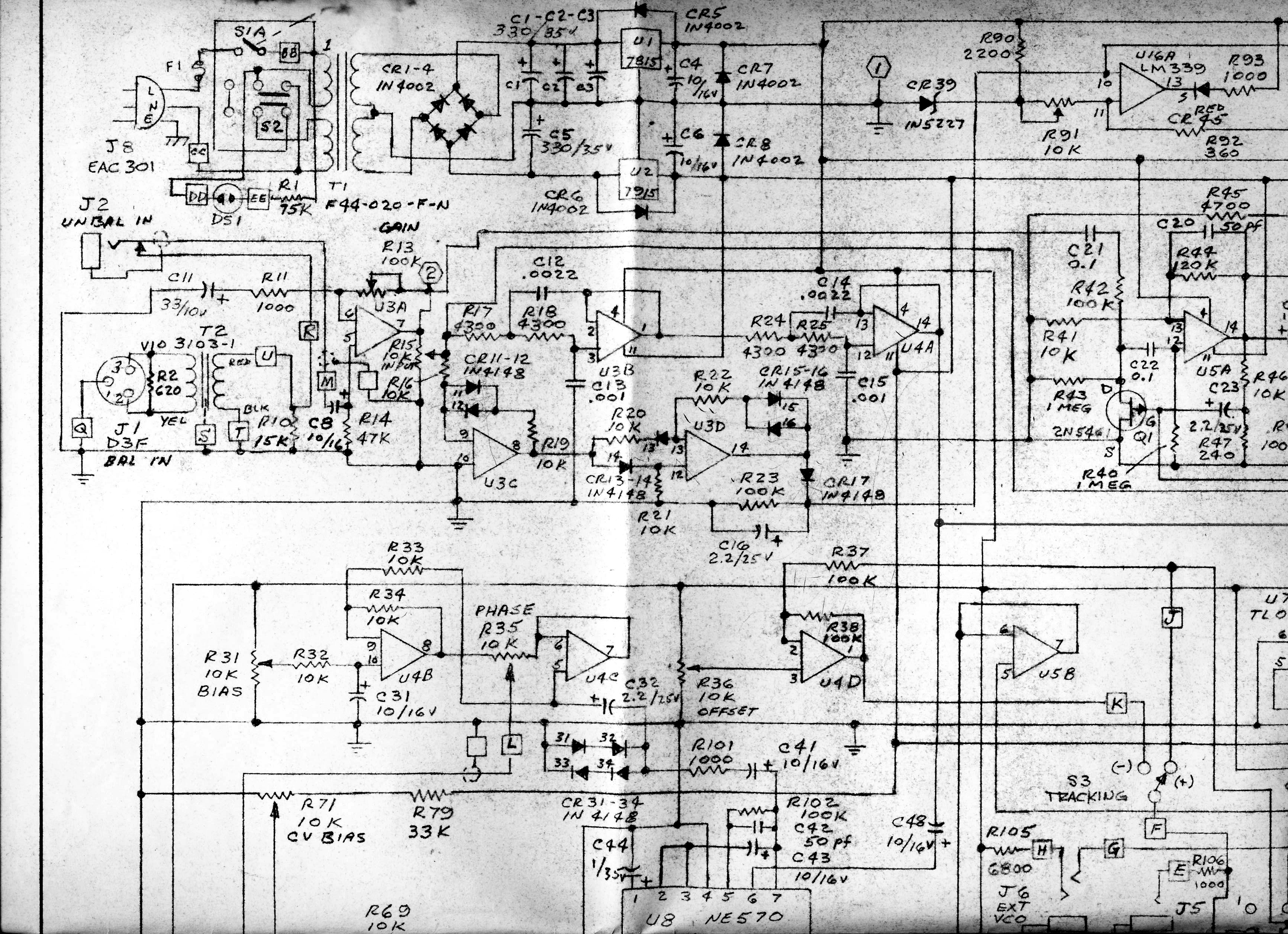
Going through some old drawings one afternoon I found the schematics for the DynaFlanger I designed with Bill Hall at MicMIx over 30 years earlier. Had no idea people remembered this stuff...
Edit 12/29/13. There are better schematics and a circuit description in this thread: viewtopic.php?f=12&t=612
http://www.ka-electronics.com/images/jp ... _Tile1.JPG
http://www.ka-electronics.com/images/jp ... _Tile2.JPG
http://www.ka-electronics.com/images/jp ... _Tile3.JPG
http://www.ka-electronics.com/images/jp ... _Tile4.JPG
MicMix DynaFlanger Schematics
-
mediatechnology

- Posts: 5456
- Joined: Sat Aug 11, 2007 2:34 pm
- Location: Oak Cliff, Texas
- Contact:
Re: MicMix DynaFlanger Schematics
Hey Wayne,
Great site! An abundance of useful information!
It's time we clear the dust from this thread and bring a DynaFlanger back into the spotlight.
A gentleman from across the pond and me have decided to begin a joint DIY venture. We would like to build a Dynaflanger!
I've been busy studying the schematics that you have provided here and on other sites on the web.
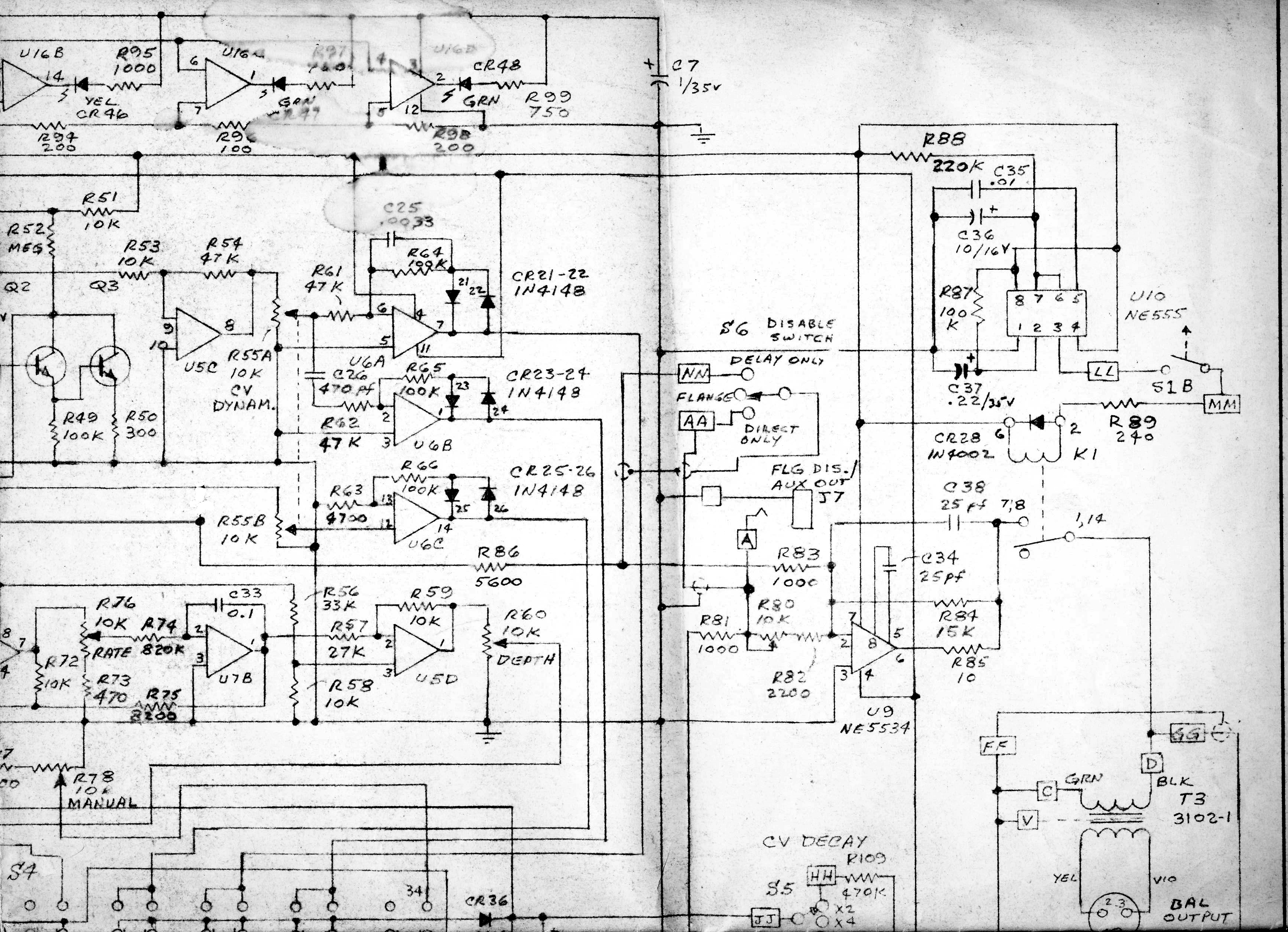
I taped together the four "tiles" to make a complete schematic but, there's a bit of a problem with the posted tiles.
The "seam" where the four tiles meet is cut off to where there is missing information.
I have searched the web for other copies....but they are all the same.
I've searched for the Maintenance and calibration manual mentioned in the operating instructions...but drew a blank.
Can you lead me in the right direction to find any additional documentation on this legendary flanger?
Great site! An abundance of useful information!
It's time we clear the dust from this thread and bring a DynaFlanger back into the spotlight.
A gentleman from across the pond and me have decided to begin a joint DIY venture. We would like to build a Dynaflanger!
I've been busy studying the schematics that you have provided here and on other sites on the web.
I taped together the four "tiles" to make a complete schematic but, there's a bit of a problem with the posted tiles.
The "seam" where the four tiles meet is cut off to where there is missing information.
I have searched the web for other copies....but they are all the same.
I've searched for the Maintenance and calibration manual mentioned in the operating instructions...but drew a blank.
Can you lead me in the right direction to find any additional documentation on this legendary flanger?
-
mediatechnology
- Posts: 5456
- Joined: Sat Aug 11, 2007 2:34 pm
- Location: Oak Cliff, Texas
- Contact:
Re: MicMix DynaFlanger Schematics
Well thank you.
Let me dig out the old copies and re-scan/tile them.
May take a few days.
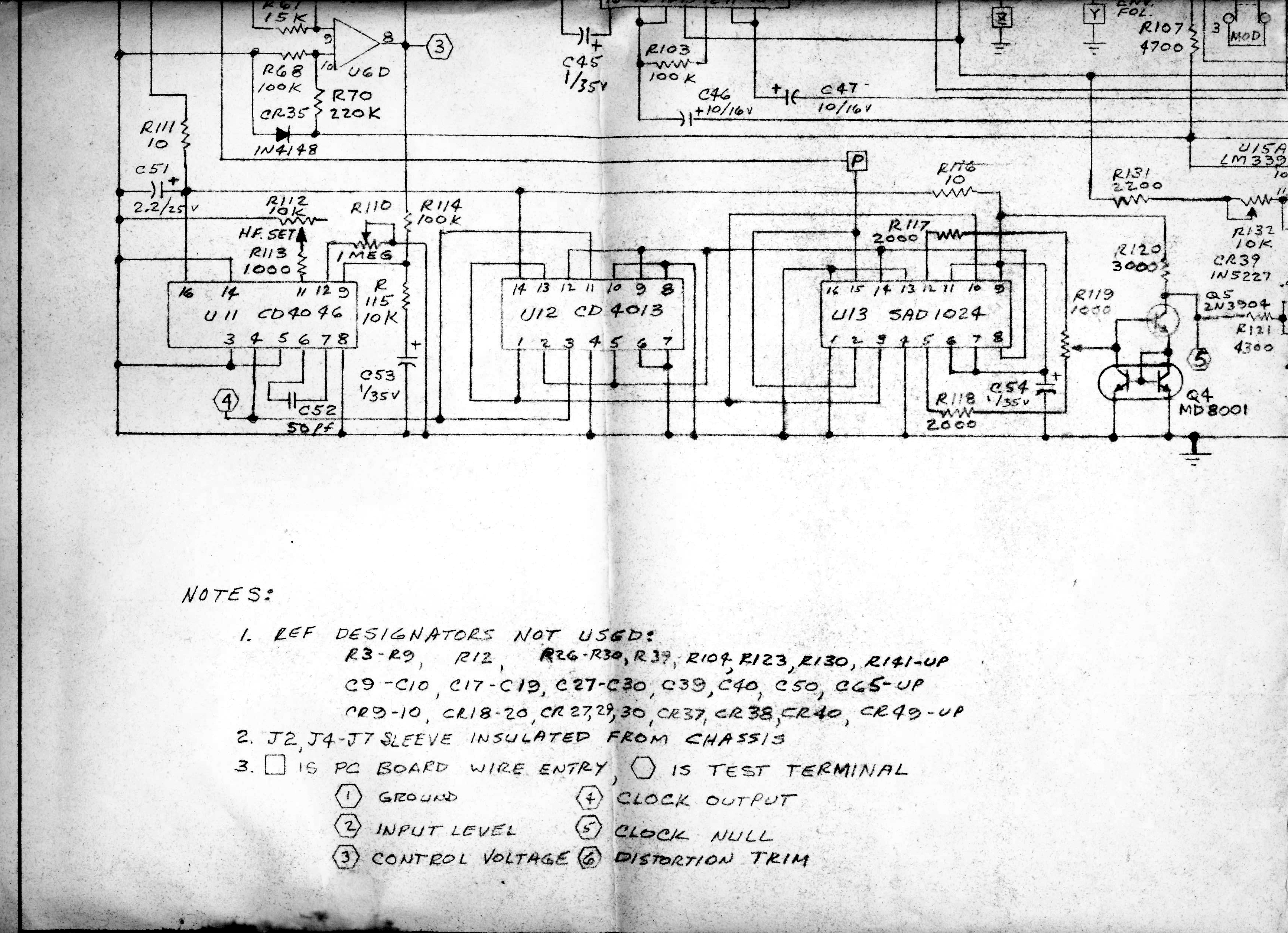
There is one thing I would change and that would be to add exponential response to the control voltage.
I did that in a prototype and it tracked far, far better.
What you gonna use for a BBD?
The Cool Audio 3005?
Let me dig out the old copies and re-scan/tile them.
May take a few days.
There is one thing I would change and that would be to add exponential response to the control voltage.
I did that in a prototype and it tracked far, far better.
What you gonna use for a BBD?
The Cool Audio 3005?
Re: MicMix DynaFlanger Schematics
Hi Wayne,
Thanks for the reply.
If you would be so gracious as to make new copies......that would be great! Thank you!
I have read on a few sites where you mentioned a exponential converter ahead of the VCO as an improvement to the circuit.
What do you have in mind? Do you have an example of a converter circuit that would work well in this application?
BBDs.....Since only one half of the original SAD1024 is being used in the Dynaflanger for 512 stages, that gives me a few options for BBDs.
I have a few SAD2014s but I don't want to "waste" them for use of half an IC. I could use a MN3004, or perhaps a TDA1022 for 512 stages...but I think the best bet would be a SAD512.
I sourced one of these BBDs thinking that there were effects I could build with it. It turns out that the 512 used in all of the effects is the SAD512D. The D version is an DIL8 package that only requires one clock signal and creates the other clock signal internally. SAD512D = different animal!
So...the DIL16 SAD that I have has the Dynaflanger's name all over it!
I read through the VCA based phaser thread in the forum...has there been any more work on that? It looks very interesting!
-
mediatechnology
- Posts: 5456
- Joined: Sat Aug 11, 2007 2:34 pm
- Location: Oak Cliff, Texas
- Contact:
Re: MicMix DynaFlanger Schematics
The SAD1024 in the Dynaflanger used the interleaved "parallel multiplex" connection so half of it wasn't exactly wasted.
We did this for lower THD and higher DR.
But the net was a 512 stage line and SAD1024s were available.
For the expo I used a simple two transistor/two op amp antilog converter.
I may be able to find that sch but it's similar to what can be found in National Semi documents or the Op Amp Cookbook.
I haven't done much on the VCA-based phaser recently.
Re: MicMix DynaFlanger Schematics
I just reviewed the SAD configuration a bit closer when I realized that it was a parallel multiplex configuration right out of the data sheet.
I hopped on the site to correct my earlier statement....to find that you corrected it for me!
Thanks for the info on the converter. I'll do a bit of research and see what I come up with.
I just finished a project that I'm pretty proud of. I made a clone of a Mutron Flanger.
I housed it in a Morley Optical Volume enclosure. This enclosure made sense since the Mutron uses a similar pedal/shutter LED/LDR technology for the pedal sweep.
I look forward to tackling the Dynaflanger!
Re: MicMix DynaFlanger Schematics
I found the National log converter document with example circuits to improve the response of the VCO section.
http://users.ece.gatech.edu/~lanterma/s ... /AN-30.pdf
I also found a stash of LM394s that I had! Thanks for pointing me in the right direction.
I've been thinking about BBD alternatives.
I can use the original SAD1024 for my build, but if anyone else wants to build a Dynaflanger, they will have to source a 1024 at an exorbitant cost, if they can find one!
In recent years there has been success clocking a buffered MN3007 at a higher frequency, well past 1MHz.
I might look into using two 3007s in a parallel multiplex configuration, with the clock lines buffered with a 4049.
It's worth a look and some testing.
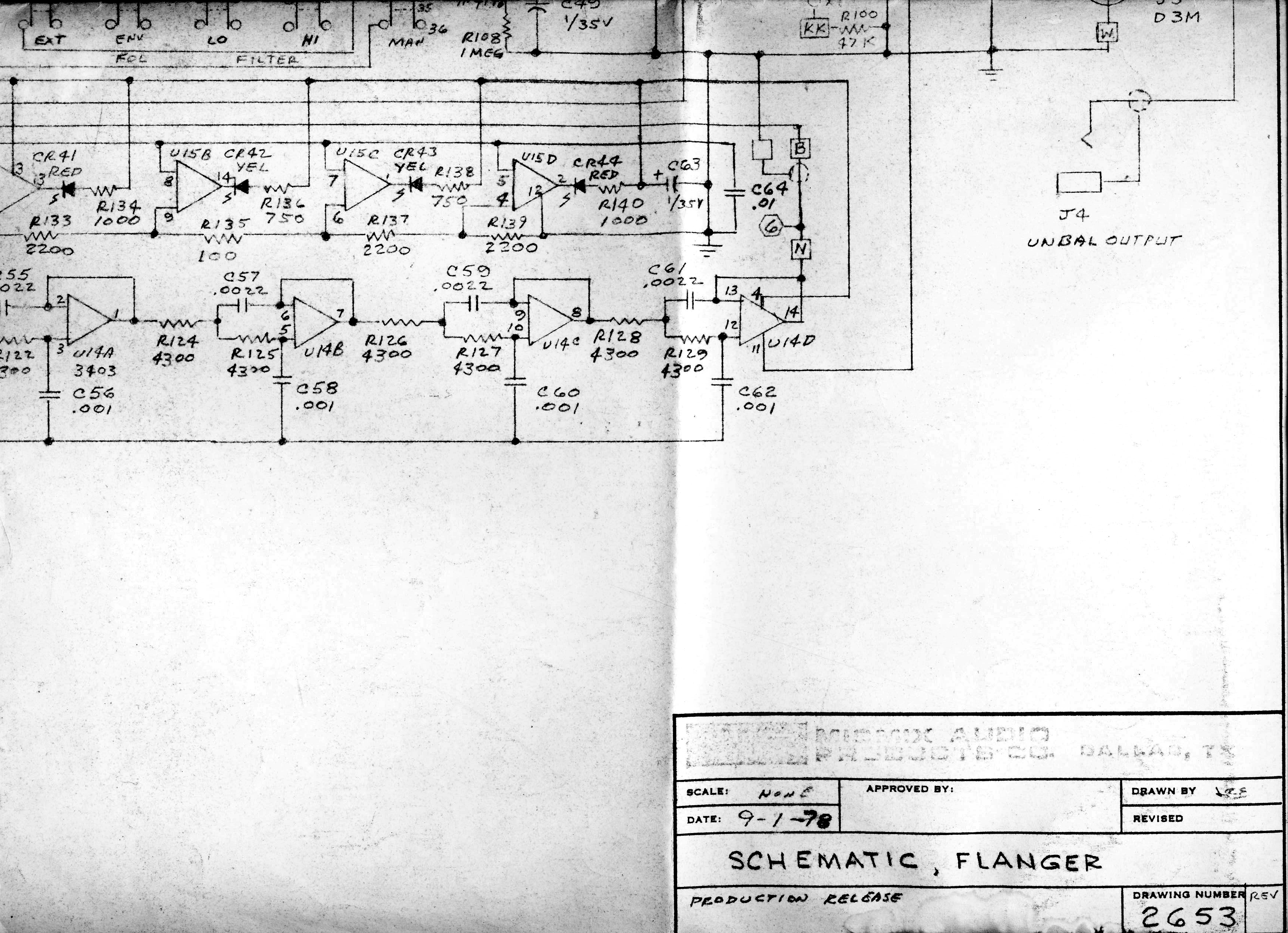
I have a question Wayne.
The drawing depicts U14 as being a 3403 op amp. Are the rest of the unmarked quad op amps in the original Dynaflanger 3403s as well?
http://users.ece.gatech.edu/~lanterma/s ... /AN-30.pdf
I also found a stash of LM394s that I had! Thanks for pointing me in the right direction.
I've been thinking about BBD alternatives.
I can use the original SAD1024 for my build, but if anyone else wants to build a Dynaflanger, they will have to source a 1024 at an exorbitant cost, if they can find one!
In recent years there has been success clocking a buffered MN3007 at a higher frequency, well past 1MHz.
I might look into using two 3007s in a parallel multiplex configuration, with the clock lines buffered with a 4049.
It's worth a look and some testing.
I have a question Wayne.
The drawing depicts U14 as being a 3403 op amp. Are the rest of the unmarked quad op amps in the original Dynaflanger 3403s as well?
Re: MicMix DynaFlanger Schematics
Hey Wayne,
Thanks so much for reposting the schematics!
It's time to get "dug in" on this one!
Thanks so much for reposting the schematics!
It's time to get "dug in" on this one!
Re: MicMix DynaFlanger Schematics
Wayne,
I'm the 'gentleman from across the pond' that armdnrdy refers to.
Just thought I'd give you a 'heads up'.

Regards
Andy
I'm the 'gentleman from across the pond' that armdnrdy refers to.
Just thought I'd give you a 'heads up'.
Regards
Andy

Re: MicMix DynaFlanger Schematics
I don't know if you are looking for some unsolicited advice, but that doesn't usually stop me. 
If you are doing a new design in this century you might investigate BBDs that are still being manufactured. I think there is a Chinese fab making licensed (0r not) versions of the old MN series. IMO It would be incredibly painful to get a new design up and working only to have your precious cache of obsolete SADxxxx BBDs stop working. Designing to work with a production part means you will not face that potential unpleasantness. In fact if you have a stash of old SAD1024 or other variants you can probably sell them for a good premium to people trying to keep their old studio soldiers running. I still hear from customers using the old LOFT delay/flangers that used the SAD chips, and the old obsolete parts are getting harder to find.
Like Wayne I am a little fuzzy about design details of my old work, unlike Wayne, I did not keep schematics of my old stuff. In fact a couple years ago I sent a huge pile of spec sheets and applications notes from my personal BBD/CCD files (including early phillips BBD, Panasonic/Matsushita, and later Reticon) , to a guy who promised to scan them in and share them on the WWW . No I don't remember his name either but it was from a discussion on gearslutz a few years back. I mailed him several pounds of obscure literature, better than sending it to a landfill when I croak.
Getting back on topic and speaking in broad strokes, I would be a little less focused on path THD and look for the shortest practical BBD out there (I think I used a Reticon 512D for a studio flanger, while i used a MN3001 in an earlier kit article flanger). I recall when I changed from a higher distortion OTA based NR to the newer NE570/572 companders I had customers comment that they preferred the former higher distortion designs. Keep in mind that about the only reason to use a BBD in 2014 for delay is for the characteristic path distortion.
  Note: you could flange through zero using two delay paths, while clocking them differently introduces a need for rigorous output LPF to prevent clock noise beating. You want the two paths to have similar amplitude and phase response for deepest flanging nulls.
OK another broad stroke observation, i think i found that using a linear voltage-to-period convertor gave a more pleasing clock control law for flanging, while this is surely subjective.
Using a clean sheet for new design I might be tempted to use a THAT VCA based NR, while in my experience the cleaner NR path is not paramount and THD will be dominated by the BBD linearity. Executing a NR around a short delay flanger you will probably get best results connecting the encode and decode control voltages to each other. For longer delays you need to extract the decode control voltage separately and that is a longer discussion.
Good luck and have fun...
JR
If you are doing a new design in this century you might investigate BBDs that are still being manufactured. I think there is a Chinese fab making licensed (0r not) versions of the old MN series. IMO It would be incredibly painful to get a new design up and working only to have your precious cache of obsolete SADxxxx BBDs stop working. Designing to work with a production part means you will not face that potential unpleasantness. In fact if you have a stash of old SAD1024 or other variants you can probably sell them for a good premium to people trying to keep their old studio soldiers running. I still hear from customers using the old LOFT delay/flangers that used the SAD chips, and the old obsolete parts are getting harder to find.
Like Wayne I am a little fuzzy about design details of my old work, unlike Wayne, I did not keep schematics of my old stuff. In fact a couple years ago I sent a huge pile of spec sheets and applications notes from my personal BBD/CCD files (including early phillips BBD, Panasonic/Matsushita, and later Reticon) , to a guy who promised to scan them in and share them on the WWW . No I don't remember his name either but it was from a discussion on gearslutz a few years back. I mailed him several pounds of obscure literature, better than sending it to a landfill when I croak.
Getting back on topic and speaking in broad strokes, I would be a little less focused on path THD and look for the shortest practical BBD out there (I think I used a Reticon 512D for a studio flanger, while i used a MN3001 in an earlier kit article flanger). I recall when I changed from a higher distortion OTA based NR to the newer NE570/572 companders I had customers comment that they preferred the former higher distortion designs.
OK another broad stroke observation, i think i found that using a linear voltage-to-period convertor gave a more pleasing clock control law for flanging, while this is surely subjective.
Using a clean sheet for new design I might be tempted to use a THAT VCA based NR, while in my experience the cleaner NR path is not paramount and THD will be dominated by the BBD linearity. Executing a NR around a short delay flanger you will probably get best results connecting the encode and decode control voltages to each other. For longer delays you need to extract the decode control voltage separately and that is a longer discussion.
Good luck and have fun...
JR
Cancel the "cancel culture", do not support mob hatred.