Preventing mic preamplifier HF oscillation
Posted: Mon Mar 04, 2019 8:42 am
A long time reader, but never had the courage to participate. This is a PRO forum anyway:)
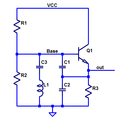
But here we go. The mic preamplifier that I recently built follows the idea of this classic circuit, except the transistors which are PNP type 2N4403.

http://www.muzines.co.uk/images_mag/art ... _large.jpg
Two channels work fine, but one has unpredictable noise behaviour, which seems to be high frequency oscillation. Textbook vs. real life I think.
The board layout may not be the main problem: small SMD components, very short connections, intact ground plane and proper power decouplings.
The question is what would be the most effective way to prevent the HF problems?
There are two solutions that I remember seeing (sorry the non electronics engineer way of thinking).
1. Adding a few hundred pF capacitor from base to emitter. I guess the idea is to short the input at the high frequencies the same way as a base to ground capacitor in a simple common emitter gain stage.
2. A ferrite bead in series with the emitter. When thinking about a common emitter amplifier again, that makes sense. The ferrite acts like an emitter resistor at very high frequencies and reduces the gain at tens or hundreds of MHz where the oscillation most likely happens. There are physically large components (parasitic inductance and capacitance) tied directly to the emitters. Sounds like a good idea to "isolate" them at high frequencies.
I know that you can get lower distortion with complementary transistor pair or op-amp feedback and that there are a number of purpose made integrated circuits available. But this version is low power and good enough at the moment. And I prefer to get a simple circuit fully working first and hopefully better understand how it works (despite the non technical backgound). After that it is time for more advanced circuits.
But here we go. The mic preamplifier that I recently built follows the idea of this classic circuit, except the transistors which are PNP type 2N4403.
http://www.muzines.co.uk/images_mag/art ... _large.jpg
Two channels work fine, but one has unpredictable noise behaviour, which seems to be high frequency oscillation. Textbook vs. real life I think.
The board layout may not be the main problem: small SMD components, very short connections, intact ground plane and proper power decouplings.
The question is what would be the most effective way to prevent the HF problems?
There are two solutions that I remember seeing (sorry the non electronics engineer way of thinking).
1. Adding a few hundred pF capacitor from base to emitter. I guess the idea is to short the input at the high frequencies the same way as a base to ground capacitor in a simple common emitter gain stage.
2. A ferrite bead in series with the emitter. When thinking about a common emitter amplifier again, that makes sense. The ferrite acts like an emitter resistor at very high frequencies and reduces the gain at tens or hundreds of MHz where the oscillation most likely happens. There are physically large components (parasitic inductance and capacitance) tied directly to the emitters. Sounds like a good idea to "isolate" them at high frequencies.
I know that you can get lower distortion with complementary transistor pair or op-amp feedback and that there are a number of purpose made integrated circuits available. But this version is low power and good enough at the moment. And I prefer to get a simple circuit fully working first and hopefully better understand how it works (despite the non technical backgound). After that it is time for more advanced circuits.