A Simple Two Channel Eight Step Bar Graph Audio Level Meter For Outboard Gear Without Using An LM3914, LM3915 or LM3916
Posted: Sat Jul 27, 2019 5:07 pm
This thread describes a simple comparator-based replacement bar graph display for the discontinued LM3915, LM3916 and almost-discontinued LM3914.
I needed a simple LED bar graph display for the XL-305 reverb clone to read reverb return level. In years past this was easily done with an LM391X bar graph driver. In this particular case I only needed eight LEDs with 3 dB steps to read from -12 to +9 dB.
We've discussed on this forum the many virtues of using a microprocessor for display and even "direct conversion" of the raw A/D data. For high dynamic range displays with a large number of LEDs using a micro makes great sense.
For this project I wanted a code-free, EMI-free, conventional analog solution.

An LM324-based simple two channel eight step audio level meter for outboard gear.
The LM324 Quad Op Amp As A Comparator
When I first started doing simple bar graphs the "go to" IC was the LM339 (quad) or LM393 (dual) comparator. Most bargraph designs you see that don't use the LM391X are based on this comparator family. The LM339 is a mix of comparator with op amp characterstics for low speed signals. It is unlike the early µA710, LM311 and the many high-speed comparators that followed. The LM339 has an open collector output.
Without hysteresis the LM339, like most comparators, will oscillate on transitions. The slowly changing envelopes of rectified audio can trigger oscillation bursts. Adding hysteresis requires two resistors per comparator. For 16 LEDs (2 channels) that's 32 resistors...
I first saw the LM324 low power op amp used as a bar graph in the SSL 4000 and 6000 82E10 dynamics card and it immediately made sense. The LM324 is a horrible op amp for audio but its low bandwidth, low gain and class-B output are considered features for this application. They're too slow to oscillate but do have decent DC performance. Despite their low power they can still source and sink considerable current. For these reasons they make great bar graph comparators. An image search shows that plenty of others folks have had this same idea. The LM324 and LM324A (improved) are dirt cheap, mature, and have modern applications in industrial control and consumer products.
One advantage that the LM324 or LM339 have over the LM391X is that the LED current returns to the -15V rail. The LM391X's LED current flows into ground.
Speaking of the power supply rails the LM324 and LM324A usually have a 32V supply limitation. (Some improved variants are 36V.) If one needed to run this on +/-18V rails adding a 5 to 6.8V Zener in the negative rail is a good option. It's what SSL did for the 82E10 card. Though the regulation is poor compared to a regulator it doesn't affect LED brightness or metering accuracy.
Shared Reference Voltage Divider
Sharing the reference divider between two channels conserves resistors.
An LM334 current source, set to 1 mA, feeds the reference divider string. A current source virtually eliminates supply voltage changes to the comparator reference voltages. 1 mA was chosen as a nice round number that would also use a low impedance divider string. The total resistance of the divider string is about 1.56KΩ. The reference accuracy is about 5% or 0.4 dB. A trim can be added to the LM334 in series with the 68.1Ω resistor if needed.
I used a spreadsheet to calculate the dB to Volts conversion. What's convenient about a 1 mA Iref is that the threshold voltage, in mV, is equal to Rladder * Iref. If you sum the resistance values at a particular node to ground and then multiply that by 1 mA you have the step voltage. So the lowest step, at 140 mV, has a 140Ω resistor to ground and the highest step, at 1.56 V, is about 1.56KΩ.
If I were to use this often I'd write a spreadsheet that I could plug in the dB or linear mV step size and have it calculate the R values.
Level Detector
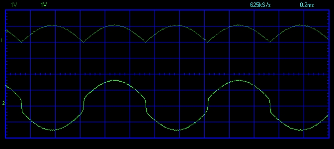
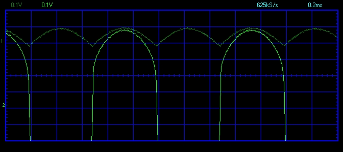
The level detector isn't anything special and there are a great many ways to accomplish full-wave rectification particularly over a limited 21 dB dynamic range. The first stage is a "pre-distorter" to overcome the forward voltage drop of the second stage rectifiers. A 5532 was used here simply because they are already on the bill of materials. A TL072 would work equally well.
The rectifier chosen has one simple advantage in that the gain can be changed by varying only the input resistor.
An averaging VU-like response was wanted. Using "99% of the steady-state value in 300 ms" works out to be a tau of 65 ms. Though a 1% value is shown to set the attack and decay (both 300 ms) unless the C is selected (or a 5% tantalum) capacitor accuracy will affect timing. Since the measurement is of a reverb return a 10 or 20% electrolytic ought to be just fine.
The internal operating "0" level at the meter inputs is -2 dBu RMS. (Line drivers and receivers scale the internal levels of most gear down and up by 6 db to preserve internal headroom. With a +4 dBu input the internal level is -2 dBu.)
With a unity gain detector the average value of a full-wave rectified -2 dBu RMS (614 mV RMS) sine wave is about 0.55V. Thus, the comparator reference voltage for a 0 dB indication is also 0.55V.
For +4 dBu RMS "0 dB" calibration the input resistors scale to 20KΩ.
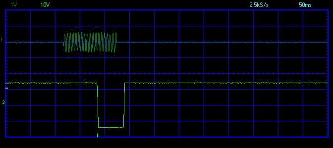
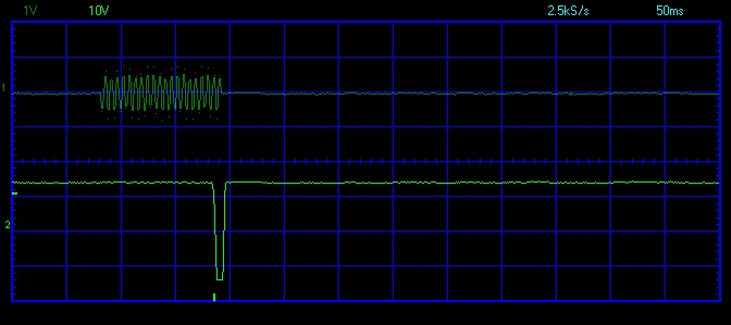
Freedom from comparator oscillation.
I checked the Protoboard looking at a lot of nodes for any hint of RF bursts on comparator transitions and just don't see any. That's very difficult to achieve with an LM339 without hysteresis. The low gain of the LM324, when used as a comparator, causes ramped, slew-limited output transitions to the LEDs.
Next Up.
The GR-10 and GR-20 meters we did for the Pico compressors was a very popular seller. I'm not planning on making more of those using the discontinued LM3914 but I would like to show a linear-scaled gain reduction/control voltage meter front end.
Also, to make JR happy and use a micro for display I'll be using the analog level detector to feed an Arduino Nano driving an WSM2812 RGB display. The Arduino isn't up to doing the DSP but it will drive some pretty LEDs quite well. That will be a "disco" VU meter.
I needed a simple LED bar graph display for the XL-305 reverb clone to read reverb return level. In years past this was easily done with an LM391X bar graph driver. In this particular case I only needed eight LEDs with 3 dB steps to read from -12 to +9 dB.
We've discussed on this forum the many virtues of using a microprocessor for display and even "direct conversion" of the raw A/D data. For high dynamic range displays with a large number of LEDs using a micro makes great sense.
For this project I wanted a code-free, EMI-free, conventional analog solution.
An LM324-based simple two channel eight step audio level meter for outboard gear.
The LM324 Quad Op Amp As A Comparator
When I first started doing simple bar graphs the "go to" IC was the LM339 (quad) or LM393 (dual) comparator. Most bargraph designs you see that don't use the LM391X are based on this comparator family. The LM339 is a mix of comparator with op amp characterstics for low speed signals. It is unlike the early µA710, LM311 and the many high-speed comparators that followed. The LM339 has an open collector output.
Without hysteresis the LM339, like most comparators, will oscillate on transitions. The slowly changing envelopes of rectified audio can trigger oscillation bursts. Adding hysteresis requires two resistors per comparator. For 16 LEDs (2 channels) that's 32 resistors...
I first saw the LM324 low power op amp used as a bar graph in the SSL 4000 and 6000 82E10 dynamics card and it immediately made sense. The LM324 is a horrible op amp for audio but its low bandwidth, low gain and class-B output are considered features for this application. They're too slow to oscillate but do have decent DC performance. Despite their low power they can still source and sink considerable current. For these reasons they make great bar graph comparators. An image search shows that plenty of others folks have had this same idea. The LM324 and LM324A (improved) are dirt cheap, mature, and have modern applications in industrial control and consumer products.
One advantage that the LM324 or LM339 have over the LM391X is that the LED current returns to the -15V rail. The LM391X's LED current flows into ground.
Speaking of the power supply rails the LM324 and LM324A usually have a 32V supply limitation. (Some improved variants are 36V.) If one needed to run this on +/-18V rails adding a 5 to 6.8V Zener in the negative rail is a good option. It's what SSL did for the 82E10 card. Though the regulation is poor compared to a regulator it doesn't affect LED brightness or metering accuracy.
Shared Reference Voltage Divider
Sharing the reference divider between two channels conserves resistors.
An LM334 current source, set to 1 mA, feeds the reference divider string. A current source virtually eliminates supply voltage changes to the comparator reference voltages. 1 mA was chosen as a nice round number that would also use a low impedance divider string. The total resistance of the divider string is about 1.56KΩ. The reference accuracy is about 5% or 0.4 dB. A trim can be added to the LM334 in series with the 68.1Ω resistor if needed.
I used a spreadsheet to calculate the dB to Volts conversion. What's convenient about a 1 mA Iref is that the threshold voltage, in mV, is equal to Rladder * Iref. If you sum the resistance values at a particular node to ground and then multiply that by 1 mA you have the step voltage. So the lowest step, at 140 mV, has a 140Ω resistor to ground and the highest step, at 1.56 V, is about 1.56KΩ.
If I were to use this often I'd write a spreadsheet that I could plug in the dB or linear mV step size and have it calculate the R values.
Level Detector
The level detector isn't anything special and there are a great many ways to accomplish full-wave rectification particularly over a limited 21 dB dynamic range. The first stage is a "pre-distorter" to overcome the forward voltage drop of the second stage rectifiers. A 5532 was used here simply because they are already on the bill of materials. A TL072 would work equally well.
The rectifier chosen has one simple advantage in that the gain can be changed by varying only the input resistor.
An averaging VU-like response was wanted. Using "99% of the steady-state value in 300 ms" works out to be a tau of 65 ms. Though a 1% value is shown to set the attack and decay (both 300 ms) unless the C is selected (or a 5% tantalum) capacitor accuracy will affect timing. Since the measurement is of a reverb return a 10 or 20% electrolytic ought to be just fine.
The internal operating "0" level at the meter inputs is -2 dBu RMS. (Line drivers and receivers scale the internal levels of most gear down and up by 6 db to preserve internal headroom. With a +4 dBu input the internal level is -2 dBu.)
With a unity gain detector the average value of a full-wave rectified -2 dBu RMS (614 mV RMS) sine wave is about 0.55V. Thus, the comparator reference voltage for a 0 dB indication is also 0.55V.
For +4 dBu RMS "0 dB" calibration the input resistors scale to 20KΩ.
Freedom from comparator oscillation.
I checked the Protoboard looking at a lot of nodes for any hint of RF bursts on comparator transitions and just don't see any. That's very difficult to achieve with an LM339 without hysteresis. The low gain of the LM324, when used as a comparator, causes ramped, slew-limited output transitions to the LEDs.
Next Up.
The GR-10 and GR-20 meters we did for the Pico compressors was a very popular seller. I'm not planning on making more of those using the discontinued LM3914 but I would like to show a linear-scaled gain reduction/control voltage meter front end.
Also, to make JR happy and use a micro for display I'll be using the analog level detector to feed an Arduino Nano driving an WSM2812 RGB display. The Arduino isn't up to doing the DSP but it will drive some pretty LEDs quite well. That will be a "disco" VU meter.