
Wow.. good work guys... 10-15 mV on a DC coupled 60dB gain stage could be real interesting.. Good useful data.
Knowing what to expect is really good to know.
Good progress.. when do we design our uber console?
JR
Old: A Direct-Coupled Input-Capacitorless Active Mic Preamp
Re: A Direct-Coupled Input-Capacitorless Active Mic Preamp
Cancel the "cancel culture", do not support mob hatred.
Re: A Direct-Coupled Input-Capacitorless Active Mic Preamp
Wayne,
I'm looking at this preamp and I like it more and more. I'm thinking of building something like a 4- or 8-channels pre (hope to fit it in 1U case) and I'm leaning towards your design.
I thought that some sort of "Signal" and "Clip" indicators would be useful, and I remember the circuit you suggested (http://www.tenmilecreek.net/images/jpg/level_meter2.jpg) that is powered from 12/24V which fits nicely into the power scheme of the preamp. I thought of taking the juice for 12V regulation from the same secondary that is used for the buffer circuitry.
Now, what do you think, can I take the out from the comparators to another opamp and use it for "Signal" indicator or do I need some buffering here?
- Attachments
-
- indicator.jpg (28.74 KiB) Viewed 17807 times
-
mediatechnology

- Posts: 5463
- Joined: Sat Aug 11, 2007 2:34 pm
- Location: Oak Cliff, Texas
- Contact:
Re: A Direct-Coupled Input-Capacitorless Active Mic Preamp
Thanks Ilya.
I think you could use the circuit you posted as-is or with one TL074 section eliminated or this one:

The above gives you off, signal present and clip though it's only negative peak detecting, You could combine the two for bipolar peak detection.
On the DC-coupled preamp we may want to re-visit the differential servo based on what I learned here:
https://www.proaudiodesignforum.com/for ... ?f=6&t=256
I think you could use the circuit you posted as-is or with one TL074 section eliminated or this one:
The above gives you off, signal present and clip though it's only negative peak detecting, You could combine the two for bipolar peak detection.
On the DC-coupled preamp we may want to re-visit the differential servo based on what I learned here:
https://www.proaudiodesignforum.com/for ... ?f=6&t=256
Re: A Direct-Coupled Input-Capacitorless Active Mic Preamp
Wayne,
I think that negative peak detector would suffice. However, these circuits both waste an IC "real estate": in the first one it is 1 unused op-amp and in the second it's 1 unused comparator.
The last circuit you proposed looks very reasonable. But returning to the first one, I thought that maybe it's possible to use a transistor to drive a LED, this may save us an op-amp in 074 and will make a nice 2-channel detector with single 339 and single 074.
I was also thinking about layout for the preamp. I often make a 2-sided PCBs with the top side being mostly ground plane. But since we're going to use a "sliding rail" supply there should be two grounds: one is internal reference and another is "external". I thought of combining the internally referenced parts in one physical place and make an "internal ground" plane on top of it. But then I thought: what if we do the whole circuit on the "sliding rails" (including the stages on page 2)and AC couple it only at the output driver? What do you think? Will it ever work?
EDIT: I'm going to incorporate the improved servo into the design. I'll begin putting the schematic together once I have more free time.
-
mediatechnology
- Posts: 5463
- Joined: Sat Aug 11, 2007 2:34 pm
- Location: Oak Cliff, Texas
- Contact:
Re: A Direct-Coupled Input-Capacitorless Active Mic Preamp
The first circuit is fullwave and the phase inverter could be done with a BJT. That one is portioned the way it is because of the device it was built in. (Don't remember what it was though.) The last two TL074 could actually be comparators too and only one is required for a signal present (or clip) LED.I think that negative peak detector would suffice. However, these circuits both waste an IC "real estate": in the first one it is 1 unused op-amp and in the second it's 1 unused comparator.
The last circuit you proposed looks very reasonable. But returning to the first one, I thought that maybe it's possible to use a transistor to drive a LED, this may save us an op-amp in 074 and will make a nice 2-channel detector with single 339 and single 074.
You could also use a conventional op amp diode peak detector for the first LM339 in the last circuit. For two channels it would be a TL072 and LM339. Don't forget the LM393 when you need two comparators/package. The advantage to the LM339/393 peak detector is that it's so darn fast.
 FWIW I would avoid any ground or power planes under a 1510, 1512 or 1570's input or Rgain lines. You have to balance the capacitance to ground on the inputs and avoid it entirely around the Rgain pins. Try to keep tip/ring and Rgain 1/2 loops geometrically symmetrical.
Power planes radiate Icc/Iee into the inputs and cause THD. Unfortunately this has been proven. My instincts said "don't do it" I was overruled and a new layout was eventually required.
Re: A Direct-Coupled Input-Capacitorless Active Mic Preamp
The speed of the peak detector is probably not an issue for general audio use. If anything the hold is more useful than ultra fast capture speed. I would suggest a focus, on presenting a linear load to the audio path so you don't become a source of distortion in a very high performance path. As Wayne mentioned even small things like layout make a difference in the margin. A peak detector could dump current into the ground or reflect a load onto a mid impedance line.
Comparators are purpose designed for the application so their input impedance doesn't shift dramatically when the input stage is above or below threshold. Using some old school bipolar opamps as comparators can lead to significant input bias current difference above and below threshold. Not so much with FET input opamps.
I wouldn"t lose too much sleep about spare opamps, and while you could probably do that with a single or couple transistors, they are harder to keep their input impedance flat and linear.
JR
Cancel the "cancel culture", do not support mob hatred.
Re: A Direct-Coupled Input-Capacitorless Active Mic Preamp
JR, I've played with the fullwave circuit and tried to substitute inverter or LED driver with a BJT. I must conclude that I'm not very proficient at circuit design and I'm not ready to modify this excellent circuit to get rid of an op-amp.
I think I'll go with the existing circuits as building blocks.
I'm planning to do separate PCBs: preamp, PSU and metering. I think that it'd be conveient and would give and option of different metering solutions, like "signal present/overload" or "bargraph" etc.
Wayne, speaking of ground planes, would you discourage using ground plane throughout the whole preamp board? Or should I just avoid ground planes under 1510, RGain and tip/ring?
Also, regarding inductors around RGain in the improved servo. I should choose common mode inductors, right? Any particular brands suggestions?
-
mediatechnology
- Posts: 5463
- Joined: Sat Aug 11, 2007 2:34 pm
- Location: Oak Cliff, Texas
- Contact:
Re: A Direct-Coupled Input-Capacitorless Active Mic Preamp
Guys -
I'm noticing some issues with getting logged out while trying to submit a post. I'll make this one short.
Ground planes are OK if they don't interfere with the tip/ring and Rgain areas.
I would just use regular 10 uH chokes.
I'm noticing some issues with getting logged out while trying to submit a post. I'll make this one short.
Ground planes are OK if they don't interfere with the tip/ring and Rgain areas.
I would just use regular 10 uH chokes.
Re: A Direct-Coupled Input-Capacitorless Active Mic Preamp
I've put up the preamp schematic with another servo suggested by Wayne. Here it is:
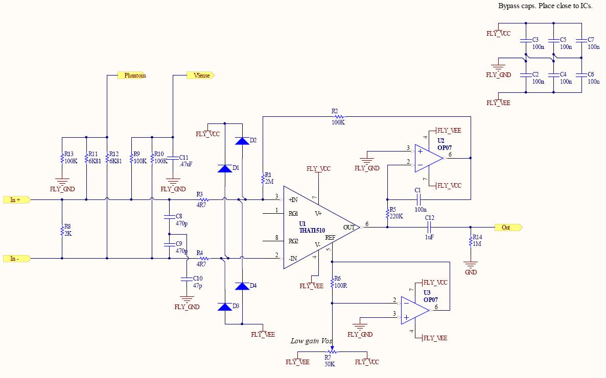
Let me know if there are any glaring errors in the circuit...
EDIT: I'm going to place as much controls on PCB as possible. I think I'll go for Grayhill 71PCB right angle switches for coarse gain and Neutriks PC mounted XLRs. Haven't decided on "Fine gain" pot and other switches yet...
Let me know if there are any glaring errors in the circuit...
EDIT: I'm going to place as much controls on PCB as possible. I think I'll go for Grayhill 71PCB right angle switches for coarse gain and Neutriks PC mounted XLRs. Haven't decided on "Fine gain" pot and other switches yet...
Re: A Direct-Coupled Input-Capacitorless Active Mic Preamp
I built 24 boards with this circuit (yea,yea, I know "Where are the photos?") and they are well liked in the studios. I did put a ground plane under them, but on the top side of the board (I didn't know any better), but careful attention was made to symmetry, both with the Rgain and Input lines (all on the bottom side of the board). So far, no problems.
Best,
Bruno2000
Best,
Bruno2000
ilya wrote:I've put up the preamp schematic with another servo suggested by Wayne. Here it is:
Let me know if there are any glaring errors in the circuit...
EDIT: I'm going to place as much controls on PCB as possible. I think I'll go for Grayhill 71PCB right angle switches for coarse gain and Neutriks PC mounted XLRs. Haven't decided on "Fine gain" pot and other switches yet...
The large print giveth, and the small print taketh away - Tom Waits