I find this bit in a TI pdf:
That touches on my only observation, which was that feedback current appears to change more drastically with Rf being varied.The Noninverting Op Amp
The actual resistor values are determined by the impedance levels that the designer wants to establish. If RF = 10K and RG = 10K the gain is two as shown in equation 2, and if RF = 100K and RG = 100K the gain is still two. The impedance levels of 10 K or 100 K determine the current drain, the effect stray capacitance will have, and a few other points. The impedance level does not set the gain; the ratio of RF/RG does.
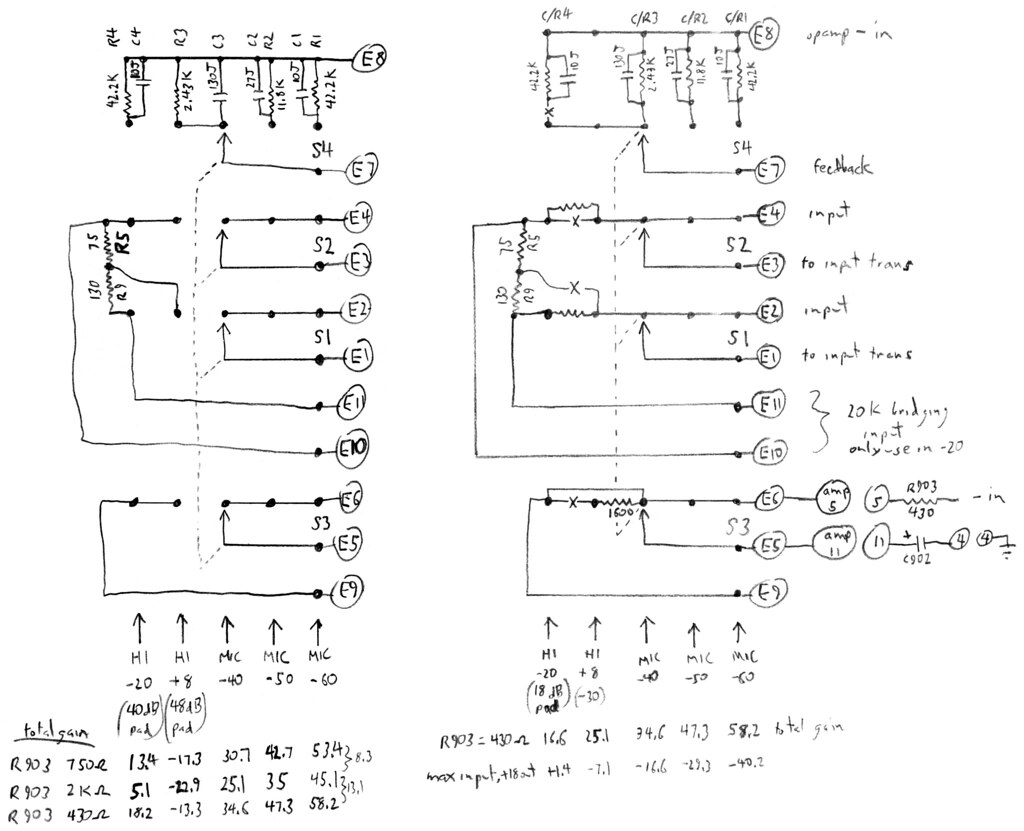
To add to the fun, at some point it appears RCA changed the value of Rg, going from a minimum gain of 6.9 dB (2k/2k43) to a minimum of 12.5 dB (750/2k43). Max Rf is 42K2, and I am about to have a listen to that with Rg 430, which would appear to move gain range up to 16.4 - 40 dB.
I imagine the crucial part of messing with Rg in this case would be the effect on the Cf's. Perhaps I'm considering messing with input Z more than I realize.
Gain (officially) steps in 10 dB increments here, and I note those steps to be most accurate with Rg 2K, and increasingly higher with reduced Rg value.
I thought about changing the gain control to an Rg rheostat, but in the end I wish to avoid trashing the original cosmetics (personal problem), and simply change some bits on the 5 position 4 pole switch, which has an unused section. Harder, for sure.
At this point, I've arrived at a theoretical plan to rework the existing stepped switch for a wider overall gain range, changing two bridging (line pad) input positions to additional mic gain points. The HI+8 point maintaining the same Rf as MIC-40 and switching in additional Rg resistance for the one position, essentially becoming MIC-30. HI-20 going back to MIC-40 gain setting, and inserting a 20 dB U pad in the mic path. Should end up with roughly 17 to 58 dB in 10 dB steps, if I'm thinking about it correctly, and there are no booby traps. The most obvious danger I see lies is putting the Rg path through a stepped switch, and having an accidental open condition. This would have both Rf and Rg in MBB switching paths.
To be tried on the bench ASAP, any thoughts or derision appreciated.


