Re: A VCA-Based Phaser
Posted: Wed Jul 21, 2010 5:00 pm
This may be an earlier citation for an SSM2164 based phaser from Osamu Hoshuyama. It's dated before Neil's Webbly World phaser. http://userdisk.webry.biglobe.ne.jp/000 ... ph0505.GIF
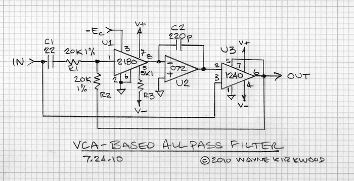
With some help from someone more skilled than I, I was able to modify the Hoshuyama circuit to use a THAT2180. Although I changed the Hoshuyama circuit to accommodate the overall non-inverting nature of the THAT VCA/I-V combination, what I didn't see in the above was the DC feedback path (R3 in the above sch) that wraps around the VCA. (R3 also provides AC feedback which is certainly more obvious.) The DC feedback provided by R3 permits the I-V stage - with Cfb made large so that it's an integrator - to run open loop without local DC feedback. Placing an Rfb in parallel with Cfb prevents the circuit from working properly. One of my errors was to return R3 to the left side of the input coupling cap (not shown) and this opened the loop at DC.
Since the THAT2180 doesn't invert overall, the sign of the DC (and AC) feedback provided by R3 requires additional inversion. This is done in the all-pass stage by reversing the inputs and taking R3 from the all-pass output. I've had a chance to breadboard one pole and it works quite well. Each pole requires a 2180 VCA and a dual BIFET op amp which is considerably simpler than the bootstrapped approach which requires three op amps. This Hoshuyama topology appears to be a far better approach.
I'll build up a few more poles and post a drawing. Since the "all-pass" stage is a differential amp - the integrator is the VCA/I-V combo - I may use a THAT1240 for summation. This will permit greater gain precision and deeper notches when summed with the direct input as well as eliminate 4 resistors per all-pass stage.

