I assume you mean keeping the same sort of network, and just floating it all, as opposed to doing a truly balanced network with 2x parts. This sounds worth hearing. I wonder what typical inductor headroom really is, and how much they differ comparing original versus the various clones, and then how additional drive would affect inductor colorations.
We see 5K1 shunt input R to the amp on the Gyraf drawing, and the original interstage transformer was a nominal 15K type, IIRC. The 1510 looks like a reasonable input situation.
What you propose makes me wonder why Pultec didn't leave the network floating in either the tube or SS versions. Habit?
LC filter experiments, in Pultec MEQ context
Re: LC filter experiments, in Pultec MEQ context
Best,
Doug Williams
Electromagnetic Radiation Recorders
Doug Williams
Electromagnetic Radiation Recorders
-
mediatechnology

- Posts: 5466
- Joined: Sat Aug 11, 2007 2:34 pm
- Location: Oak Cliff, Texas
- Contact:
Re: LC filter experiments, in Pultec MEQ context
Exactly. Leave the network as-is. Hitting the inductors harder, depending on the inductor, might sound more colorful as saturation is reached.emrr wrote:I assume you mean keeping the same sort of network, and just floating it all, as opposed to doing a truly balanced network with 2x parts. This sounds worth hearing. I wonder what typical inductor headroom really is, and how much they differ comparing original versus the various clones, and then how additional drive would affect inductor colorations.
Well, maybe not. I was assuming it was a 600:600. Thought about that on the way home. I think a three op amp INA might get the impedance level high enough, permit gain, and allow for a single pot make-up control. The third OA, a 124X, would provide CM rejection.emrr wrote:We see 5K1 shunt input R to the amp on the Gyraf drawing, and the original interstage transformer was a nominal 15K type, IIRC. The 1510 looks like a reasonable input situation.
Maybe it hummed worse or the inductor shielding depended on it being unbalanced.emrr wrote:What you propose makes me wonder why Pultec didn't leave the network floating in either the tube or SS versions. Habit?
Re: LC filter experiments, in Pultec MEQ context
If you look back at my results for varying the 5K1 shunt, you get an idea of the way the range is affected.
Best,
Doug Williams
Electromagnetic Radiation Recorders
Doug Williams
Electromagnetic Radiation Recorders
passive filter loading examples
I'll stick this here, since it's somewhat related:
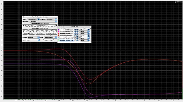
Here's some screen captures taken while looking at a passive Langevin low pass filter under varying load conditions, and some error conditions. Goes to show that with any passive filter, one needs to examine source and load environment to determine whether corrective measures are needed for proper operation.
The Langevin is the same sort of stepped and switchable passive 500/600 ohm LC circuit used by Cinema, Gates, RCA, Altec, UA, Pultec, etc etc. I believe all typically found in America pre-1970 are M-derived filters.
The color code found next to the trace names on the chart let you know what the source and load impedances were for the capture. Example: 540S 560L is 540 source Z and 560 load Z. The load Z is especially critical for overall shape, otherwise it's a wide notch.
Click this link for the full size pic
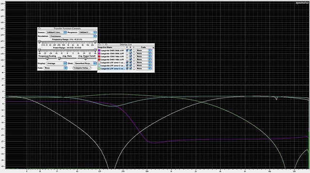
These get really fun. Here I left 'proper' operation in as a purple trace to contrast with some error conditions.
error 1: input and output common connected, output high connected, input high NOT connected
error 2: input and output common connected, input high connected, output high NOT connected
error 3: output common connected, input common NOT connected, input and output high connected
Wildy different curves.
Click this link for the full size pic
Here's some screen captures taken while looking at a passive Langevin low pass filter under varying load conditions, and some error conditions. Goes to show that with any passive filter, one needs to examine source and load environment to determine whether corrective measures are needed for proper operation.
The Langevin is the same sort of stepped and switchable passive 500/600 ohm LC circuit used by Cinema, Gates, RCA, Altec, UA, Pultec, etc etc. I believe all typically found in America pre-1970 are M-derived filters.
The color code found next to the trace names on the chart let you know what the source and load impedances were for the capture. Example: 540S 560L is 540 source Z and 560 load Z. The load Z is especially critical for overall shape, otherwise it's a wide notch.
Click this link for the full size pic
These get really fun. Here I left 'proper' operation in as a purple trace to contrast with some error conditions.
error 1: input and output common connected, output high connected, input high NOT connected
error 2: input and output common connected, input high connected, output high NOT connected
error 3: output common connected, input common NOT connected, input and output high connected
Wildy different curves.
Click this link for the full size pic
Best,
Doug Williams
Electromagnetic Radiation Recorders
Doug Williams
Electromagnetic Radiation Recorders
Re: LC filter experiments, in Pultec MEQ context
Would anyone reading this thread have a schematic for a Langevin EQ252A or its rack mount equivalent, EQ270? This is a seven-band, "graphic" eq using passive bridged-T circuits.
A colleague has one that isn't working properly.
Thanks,
-j
A colleague has one that isn't working properly.
Thanks,
-j
Re: LC filter experiments, in Pultec MEQ context
I do not. I might check with Orphan Audio, and be prepared to hold your breath.
Best,
Doug Williams
Electromagnetic Radiation Recorders
Doug Williams
Electromagnetic Radiation Recorders