In this thread JR provided us copies of his P10 and P100 phono preamps. In the thread I mention that I'm interested in building a flat preamp, without RIAA equalization, to experiment with declicking prior to RIAA equalization in software.
Update 9/5/2015: The final construction information, including schematics, circuit description parts list and board stuffing diagrams are here: https://www.proaudiodesignforum.com/for ... ?f=7&t=753
Update 8/17/2015: The current schematic for the RIAA EQ/Monitor Switcher can be found here: https://www.proaudiodesignforum.com/for ... &start=164 and the flat balanced input/balanced output moving magnet phono preamp is here: https://www.proaudiodesignforum.com/for ... &start=155
The following is a description of the original FET-based front-end:
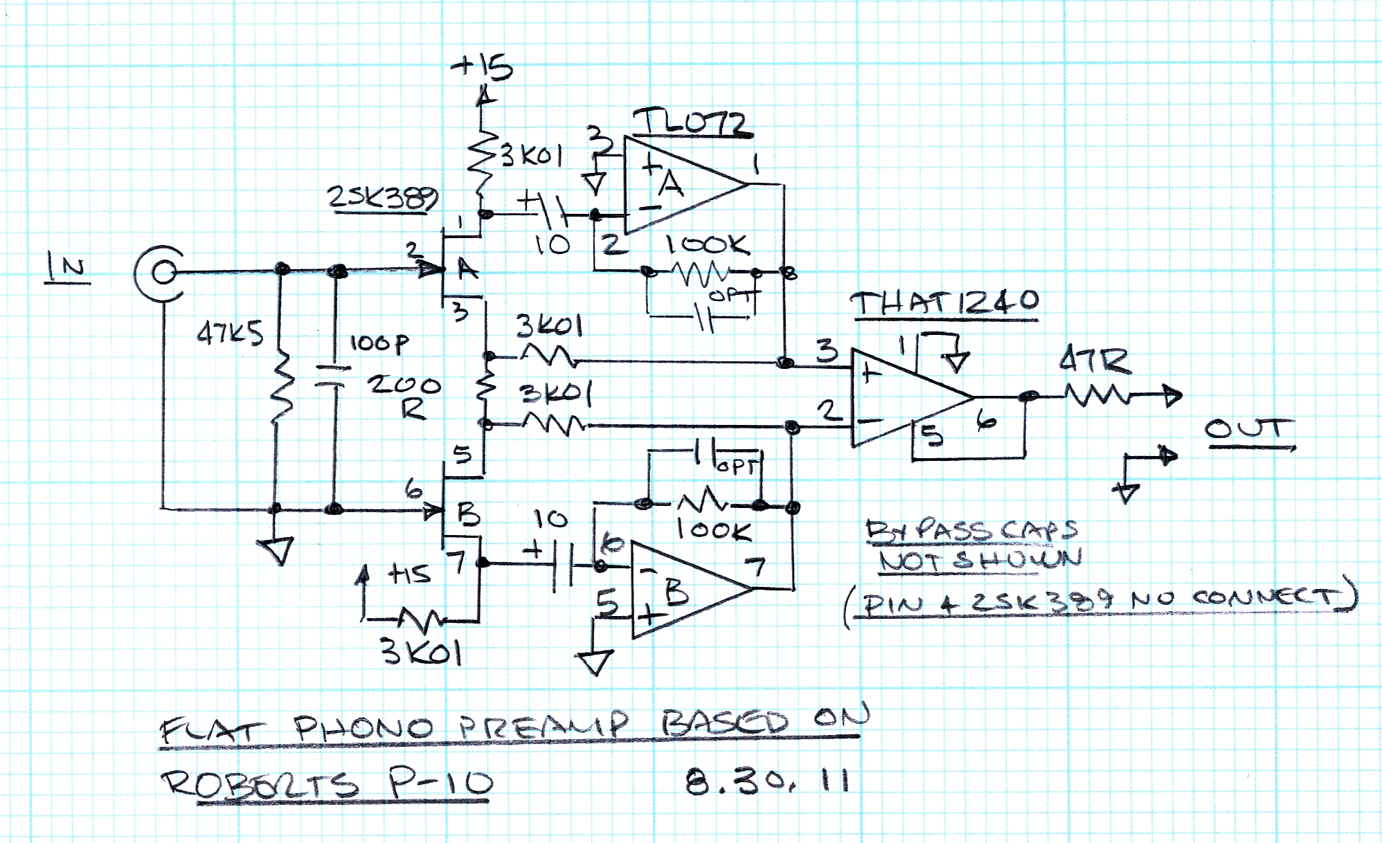
I built a flat phono preamp based on the P10 using a 2SK389 dual FET and a THAT 1240:
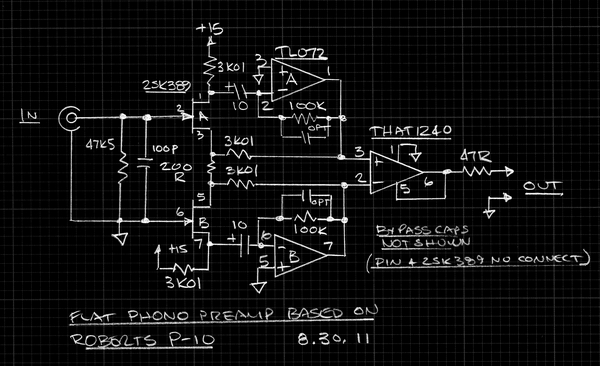
Flat Phono Preamp using 2SK389 based on Roberts P10 Front End
A large printable copy here: https://www.ka-electronics.com/images/j ... _large.JPG
Very nice THD performance:
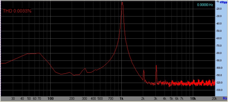
Most of the THD is generator and the output bears the generator's THD signature. I experimented with different op amps and the TL072 performed as well, if not slightly better, than an OPA2604. The optional Cc may be required for op amps having higher bandwidth. For the OPA2604 I used 10 pF to prevent oscillation.
BTW you don't have to use dual FETs. I just had some. The P10 used the PF5301: http://www.linearsystems.com/datasheets/PF5301.pdf
JR - Did you have a filter on the drain loads where they pull-up to +15?
Flat Phono Preamp Based on John's P10 and 2SK389
- mediatechnology
- Posts: 5469
- Joined: Sat Aug 11, 2007 2:34 pm
- Location: Oak Cliff, Texas
- Contact:
Re: Flat Phono Preamp Based on John's P10 and 2SK389
From the best I can reconstruct, I didn't filter the drain resistor feeds separately, but used something like 10 ohm R between 3 terminal regulator and preamp +/- V rails.*** On these rails I had one 1000uF electrolytic each and several .1uF ceramic discs by the ICs.
Noise coming in the preamp from that node is common mode so should cancel in the differential stage but an extra RxC wouldn't hurt anything.
=====
What kind of DC difference do you see between the two sources?
There is another guy revisiting this design I will link over here... .
JR
*** Note at a later date I determined that putting a 1000uF electrolytic directly across a cheap 3 terminal regulator did a nice job of complementing the rising output impedance of the modest GBW 3 terminal regulators, of course better regulators are better... In my p-100 I went way overboard on the PS noise and impedance.
Cancel the "cancel culture", do not support mob hatred.
- mediatechnology
- Posts: 5469
- Joined: Sat Aug 11, 2007 2:34 pm
- Location: Oak Cliff, Texas
- Contact:
Re: Flat Phono Preamp Based on John's P10 and 2SK389
Yeah, it appeared to be in common mode at the drain loads and I'm not seeing any issues with noise through that node. I think the P10 drawing had an arrow going to "C15." Didn't know how elaborately filtered C15 might have been. Sounds like C15 was big.
With a 2SK389V (the loose grade) and 3K3 5% resistors I'm seeing 567 and 584 mV DC across the drain loads. About 172 and 177 uA.
Low Id, but reasonably quiet and with the cartridge as a real source seems to mask any improvement one could get. I Also think I might want to run this off of batteries.
Let me put some 1% MF resistors in and re-measure match.
OK, 562 and 572 mV with 3K01 1%. 170 and 173 uA. <2% error. I must have picked a good 2SK389.
Re: Flat Phono Preamp Based on John's P10 and 2SK389
Don't bother, on account of the quiescent current, that is close enough.... while 1% will give better CM performance.
If you want to get real tweaky, metal film should have lower excess noise (from DC current) but that is also too small to bother about seriously in the context of phono cart levels.
JR
If you want to get real tweaky, metal film should have lower excess noise (from DC current) but that is also too small to bother about seriously in the context of phono cart levels.
JR
Cancel the "cancel culture", do not support mob hatred.
Re: Flat Phono Preamp Based on John's P10 and 2SK389
The stars must be aligned. I want to use this design because you can run the front end floating. I like that idea for cutting studios because ground loops and long cable runs are sometimes unavoidable.
I would like to have a better understanding of what makes this design optimized for a high source impedance. I know nothing about this aspect of design. Any help would be appreciated.
I now see why MC carts are easier to deal with. Most audio assumes a low source impedance so pretty much any mic pre could be adapted for MC use.
- mediatechnology
- Posts: 5469
- Joined: Sat Aug 11, 2007 2:34 pm
- Location: Oak Cliff, Texas
- Contact:
Re: Flat Phono Preamp Based on John's P10 and 2SK389
Thanks for posting Paul. It's an easy build.The stars must be aligned. I want to use this design because you can run the front end floating.
WRT floating: How does that work in practice regarding wiring past the tone-arm base? Do you have to re-wire from the arm base using shielded twisted pair to the preamp input?
This circuit, being differential even with the inverting input grounded and unbalanced wiring used, seems to have some advantages I haven't fully-grasped. There seems to be significantly lower THD (and hum) at the 1240 output than the SE output.
BTW Paul - If you need a balanced output use a second 1240 and reverse it's inputs relative to the existing one to make a double-balanced output stage.
Re: Flat Phono Preamp Based on John's P10 and 2SK389
Actually MC carts are well lower impedance than typical microphones,,, (mics -150-200 ohms, MC carts 10-30 ohms)Gold wrote:The stars must be aligned. I want to use this design because you can run the front end floating. I like that idea for cutting studios because ground loops and long cable runs are sometimes unavoidable.
I would like to have a better understanding of what makes this design optimized for a high source impedance. I know nothing about this aspect of design. Any help would be appreciated.
I now see why MC carts are easier to deal with. Most audio assumes a low source impedance so pretty much any mic pre could be adapted for MC use.
What makes my approach high input impedance is the JFETs.. But in practice you want to terminate with 47k to keep the MM cart happy so the high input Z is not the secret sauce you need. The magic you are looking for is floating inputs, which you could accomplish with a pair of modern low noise JFET opamps (configured as a classic instrumentation amp), but this preamp design, using the newer dual JFET Wayne specified will be very very good.
The RIAA accuracy is quite good too... better than many conventional preamps.
It even has features you may find over the top... switchable IEC/RIAA low end response.. RIAA just stops caring at 20 Hz, while IEC proposed a HPF tuned at 20 Hz. I also have an absolute polarity switch which is TMI for most people.
This was not my ultimate preamp design,,, but way better than needed and perfect for your application.
JR
Cancel the "cancel culture", do not support mob hatred.
- mediatechnology
- Posts: 5469
- Joined: Sat Aug 11, 2007 2:34 pm
- Location: Oak Cliff, Texas
- Contact:
Re: Flat Phono Preamp Based on John's P10 and 2SK389
Another advantage of FETs (or JEFET op amps) in a MM phono preamp is the low noise current FETs provide. MM cartridges have high inductance and rising impedance vs. frequency. The noise current contribution is more significant than it would be in a mic preamp where the noise voltage is typically low but the noise current high. I found the IHF cartridge model in an APT manual as (500mH+1K)||150pF.I would like to have a better understanding of what makes this design optimized for a high source impedance.
We have a 2SK389 (and LSK170) datasheet here: viewtopic.php?f=6&t=154
Re: Flat Phono Preamp Based on John's P10 and 2SK389
Those are some good hints. I will study the data sheet a little before asking a lot of questions. The only time I hear current noise discussed is in reference to input stages and summing stages. I think this is where the relationship between impedance and power matters. One basic question. Does nV/sqrtHz imply certain noise spectrum?mediatechnology wrote:MM cartridges have high inductance and rising impedance vs. frequency. The noise current contribution is more significant than it would be in a mic preamp where the noise voltage is typically low but the noise current high.
- mediatechnology
- Posts: 5469
- Joined: Sat Aug 11, 2007 2:34 pm
- Location: Oak Cliff, Texas
- Contact:
Re: Flat Phono Preamp Based on John's P10 and 2SK389
Follow this link for an ADI tutorial on Noise Spectral Density by Matt Duff.
http://www.youtube.com/watch?v=ywChrIRIXWQ