A simple mixer channel with THAT120x and THAT1646

Where we discuss new analog design ideas for Pro Audio and modern spins on vintage ones.
Post Reply
Midnightsun
Posts: 3
Joined: Fri May 04, 2012 6:15 am

A simple mixer channel with THAT120x and THAT1646

Post by Midnightsun »

Hello,

First of all, this forum is really a great source for gaining quality knowledge, especially when it comes to the usage of the THAT chips. So I’m here.

I have the plan to expand my Soundcraft Console by adding 16 additional Line Inputs and need a bit of guidance.

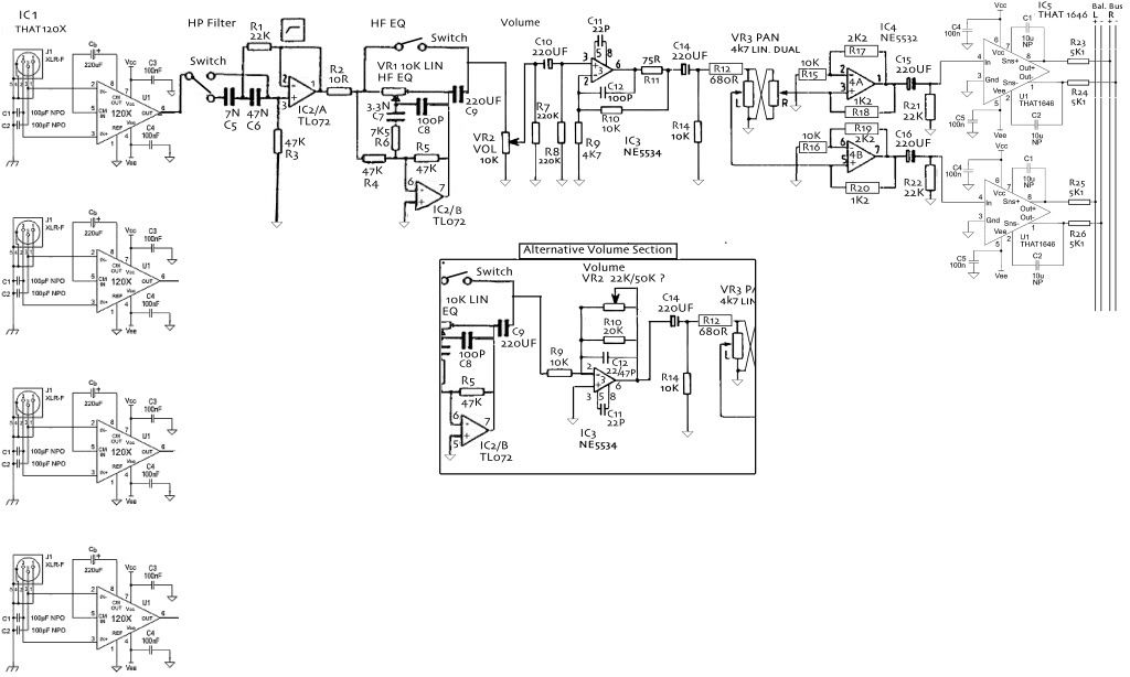
Each channel should have a Highpass Filter and a HF EQ ( for being able to ad some ‘air’ to the audio)

The 16 extra channels should have an own ballanced bus and are not connected to the console Mix-Bus. The 16 ch. bus feeds a Neumann V-475 Summing card. The balanced outputs from the V-475 card will feed internally the balanced Tape Input from the Soundcraft. From there I would be able to blend the audio into the mixers master section signal.

Just to have a starting point for a breadboard test channel, here is my idea. Each channel section is influenced by existing designs.
Any opinions and advise is very welcome
Many thanks in advance

Notes/Questions:
- C5 is 47NF and not 7NF
- I can probably drop C9
- I’m not sure about the values of R21, R22
- The values of R23 to R26 are 5.1K because the V-475 is asking for those.
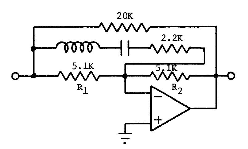
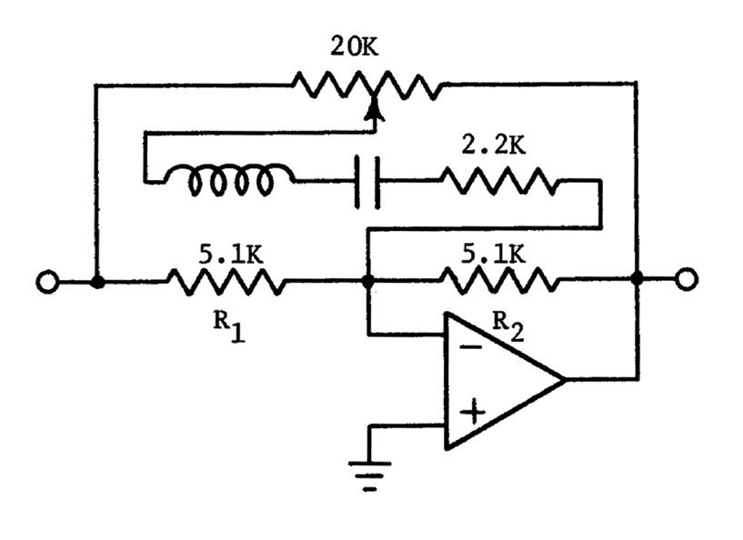
- I’m not sure about the circuit for the ‘Volume Section, see ‘Alternative Volume Section’

Image

Here is the direct link:
http://i29.photobucket.com/albums/c269/ ... Input5.jpg

The schematic in better quality also downloadable (photobucket degrades my upload a bit)
http://www.mediafire.com/download.php?yo7lolakn3trp2x
User avatar
JR.
Posts: 3709
Joined: Sat May 24, 2008 7:21 pm
Contact:

Re: A simple mixer channel with THAT120x and THAT1646

Post by JR. »

From a quick glance the HPF is non-inverting so you could just bypass around it.

The HF EQ section looks like it is missing some parts (infinite boost/cut ?), The bypass os shorting two outputs together and if it did work as drawn it would alternately add/subtract a polarity inversion.

R7 not needed.

-6dB pan law?

Volume gain stage may not need 22pf compensation at that closed loop gain.

Bypass switches may click.

JR
Cancel the "cancel culture", do not support mob hatred.
User avatar
mediatechnology
Posts: 5458
Joined: Sat Aug 11, 2007 2:34 pm
Location: Oak Cliff, Texas
Contact:

Re: A simple mixer channel with THAT120x and THAT1646

Post by mediatechnology »

Thanks for joining us midnightsun.

You could leave out C1 and C2 on the 1646 since it's driving a mix bus and would not see a SE termination. That turns off OutSmarts and you might pickup a dB or so of noise improvement.
-6dB pan law?
John - Isn't there some positive feedback around 4A and 4B? I think this circuit came from Self.
User avatar
JR.
Posts: 3709
Joined: Sat May 24, 2008 7:21 pm
Contact:

Re: A simple mixer channel with THAT120x and THAT1646

Post by JR. »

Oh yeah... I've been trying to forget that circuit. :lol:

Never mind...

JR
Cancel the "cancel culture", do not support mob hatred.
Midnightsun
Posts: 3
Joined: Fri May 04, 2012 6:15 am

Re: A simple mixer channel with THAT120x and THAT1646

Post by Midnightsun »

Thank you Gentlemen for the valuable input !

I'll adjust the schematic to that point

I'll check the HF EQ but would rather go with an inductor design. Maybe I'll find something to start with. The Pultec EQ comes to mind.

The Pan circuit comes directly from my Soundcraft 8000 desk

Would you have a preference for one of the two Volume Sections . . and if so, why : ) ?
User avatar
JR.
Posts: 3709
Joined: Sat May 24, 2008 7:21 pm
Contact:

Re: A simple mixer channel with THAT120x and THAT1646

Post by JR. »

I prefer the non-inverting volume stage, but there are pros and cons..

The non-inverting opmap stage could be configured as a differential stage by adding a pair of resistors in the + input. This could properly forward reference the ground and deliver improved fader kill, even with the fader at the end of a long wire.

The inverting stage will have lower output noise when turned down. There could be stray capacitance to ground at opamp input associated with the physical pot.

There may be a bias toward using one or the other to get polarity correct after inverting EQ stage,

I am afraid to ask why you want an inductor based EQ, so I won't.

JR
Cancel the "cancel culture", do not support mob hatred.
Midnightsun
Posts: 3
Joined: Fri May 04, 2012 6:15 am

Re: A simple mixer channel with THAT120x and THAT1646

Post by Midnightsun »

Thanks for the info

Well, I'm not afraid to answer a question that was not asked. I just like the sound of inductor based equalising.

I have not seen many circuits using inductors for the HF range.
Altough I have not figured out the L & C values for the 12.5kHz range yet, I'm looking into this princple of operation (by White Instruments):

Image
The amplifier summation resistors are equal, and without the filter controls, they give a
gain of unity (0 dB). Then if a potentiometer is connected from input to output as shown
below, it has no effect on the gain. Next the RLC circuit is added. With the pot set at
electrical center, the RLC circuit is at a balance position and has no effect on the
response. If it is turned all the way to one end, it looks as follows:
Image
At the resonant frequency f0 of the LC, the 2.2k resistance is in parallel with the 5.1k, and
the gain ratio R2/R1 is about 3/1 or +10 dB. Far away from f0, the gain returns to unity
because L or C is high in impedance and the 2.2k resistance is effectively out of the
circuit. Tuning through f gives a band-pass peak in the response that may be adjusted
from any value from 10 dB down to flat.
Conversely, if the pot is set at the other end, the gain ratio is inverted and the response is
a 10 dB notch.
The 1/3 octave bandwidth is set by the ratio of L/C, and is chosen to give a proper
addition of adjacent channel response curves.
Post Reply