Page 4 of 5
Re: RFI protection concepts
Posted: Sun Jul 20, 2014 8:20 am
by emrr
ricardo wrote:
A sorta half way house is P48V. In AES 48 2005, the P48V return is via the Chassis. This may or may not cause problems depending on loadsa stuff.
Every time I'm hand wiring a rack I get to this part and go "Huh?". Lots of contradictions in the mind when wiring 48V to chassis at the connector.
Great thread.
Re: RFI protection concepts
Posted: Sun Jul 20, 2014 8:25 am
by mediatechnology
ricardo wrote:A sorta half way house is P48V. In AES 48 2005, the P48V return is via the Chassis. This may or may not cause problems depending on loadsa stuff.
Every time I'm hand wiring a rack I get to this part and go "Huh?". Lots of contradictions in the mind when wiring 48V to chassis at the connector.
Great thread.
Thanks for posting everyone.
That approach does seem odd.
On the upside of that strategy however if the P48 or it's ground wiggles at least it's in common mode.
Re: RFI protection concepts
Posted: Sun Jul 20, 2014 8:37 am
by emrr
True
Re: RFI protection concepts
Posted: Sun Jul 20, 2014 8:45 am
by mediatechnology
I don't know if this played into the 2005 reasoning of that scenario but I have measured signal-induced common mode disturbances.
For very hot (acoustical) signals the mic I tested draws more current pulling down both legs simultaneously.
All condensor mics may not do this...
Re: RFI protection concepts
Posted: Sun Jul 20, 2014 8:02 pm
by ricardo
mediatechnology wrote:For very hot (acoustical) signals the mic I tested draws more current pulling down both legs simultaneously.
I've been guilty of designing mikes that do this.
The stick Calrecs were Class AB output cos we were the only mike maker that tried to meet an old DIN standard for P48V which only allowed 0.5mA Above 135dB spl, the output went into Class B and started drawing more current. My excuse is that at that level you probably wouldn't notice and in fact that was the case for most users.
A famous name broadcast mixer maker (who shall remain nameless but it sounds like N***) would sometimes complain cos its P48V supply wouldn't cope. But those old N***s couldn't cope with eg loadsa Schoeps mikes at once. The Schoeps was the big current hog in those days but there are bigger ones now.
This is still a problem in modified form ..
http://outrecording.com/tascam-dr-680-noise-test/
http://www.audiomastersforum.net/amforu ... l#msg77163
https://in.groups.yahoo.com/neo/groups/ ... essages/32
http://outrecording.com/down-but-not-ou ... e-problem/
I'm rather disappointed as its easy to make mike, preamp & P48v, at least, innocuous when one of these is wonky.
I don't expect my strict P48V mike designs to meet their full spec if fed eg P30V But I like the failure mode to be mostly imperceptible to the user.
Re: RFI protection concepts
Posted: Wed Jan 24, 2018 10:33 pm
by KMN
Hi. Please pardon if bumping an old thread is frowned upon.
I found this thread while googling for emi approaches.
Gertjans diagrams on page 2 seems very good. I will be redoing a couple things on my recent phono board kit build to bring it more in line with the diagram.
First question. Proper location and usage of bead L2? My balanced/differential chain vinyl ripping equipment gets it's shield grounded at the turntable The shield is capacitor terminated to earth at the adc end. I use all floating electronics. Sorry if I missed this if it was already mentioned.
Question 2: Technique for getting a low inductance bond between chassis bonded, chassis mount, metallic xlr connector bodies and it's pin 1? Any suggestions are probably going to help. I'm not a big fan of my pigtails to chassis screw. I can't really measure but am thinking the pigtails are not very good with high frequency. Maybe I could tap a "ground" screw into the connector body which I could use to terminate slightly shorter pigtails but this still seems pretty lame. There must be a better way.
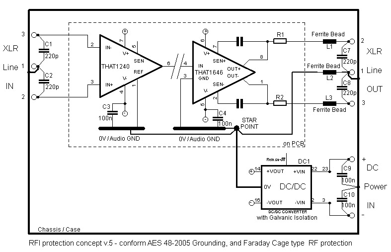
#3: filter capacitor grade? Regarding the input wye caps from the THAT1240 datasheet.... assuming the distance being spanned between filtered signal pin and the chassis bonding point is bigger than the physical dimensions of wye configured filter capacitors, the inductance shouldn't be appreciably higher than the single capacitor filters. I was thinking a little soldered sculpture of some 0603ish sized mlcc's could be doable if I could only solve question 2 from above. Are cog/npo emi filter caps going to destroy my fidelity?
Re: RFI protection concepts
Posted: Thu Jan 25, 2018 7:24 am
by mediatechnology
Hi. Please pardon if bumping an old thread is frowned upon.
I found this thread while googling for emi approaches.
Gertjans diagrams on page 2 seems very good. I will be redoing a couple things on my recent phono board kit build to bring it more in line with the diagram.
I wouldn't worry about bumping old threads here.
Not sure which diagram of his that you are referring to. You might want to link back to the post.
Even though its still in the THAT124X datasheet I don't think they recommend the Wye connection any more. The (last) current thinking on that subject at THAT was delta though that might have changed again.

Aren't your 124X in the same box as the flat preamp?
Re: RFI protection concepts
Posted: Thu Jan 25, 2018 9:05 am
by KMN
Gertjan wrote: ↑Sun Jun 01, 2014 12:12 pm
Here are the diagrams. These are the things that keep me up at night.
Sorry if I repeat myself.
I keep changing my mind about whether L2 belongs on the input or the output, trying to rationalize either way. Is one way preferred to the other?
and
I saw where you mentioned the wye may be out of favor for not being the absolute lowest inductance approach but the thought of impedance imbalance from the non wye approach is giving me a headache. That got me obsessing over whether I could come up with an equivalently low inductance wye solution to the preferred lower inductance non wye configuration and get the benefit of the wye without giving up RF performance.
If the inductance will be at a minimum when the path (RF path through the filter cap) is as direct as possible to the chassis, and the gap between the pin being filtered to it's metallic connector body represents the shortest path possible, if the physical size of the wye configured filter caps is smaller than than that gap, then the inductance of a wye may not be much higher than the lowest inductance approach, correct? There are just a few millimeters from, for example, pin 2 and pin 3 to their respective connector shells. I have very short axial lead beads soldered right to the pins. I believe if I could only find a way to fit some wye configured surface mount parts in there and find a way for the caps to make good electrical contact with the chassis tied connector near the pins, the inductance would be as low as is possible and I wouldn't be giving anything up by going with the wye in that case.
Though I am also concerned about using ceramics here. I understand they may be shunned by audio guys. Would the damage still be bad if the capacitors in these filters were ceramics considering their low capacitance values? The inductance for ceramic caps is extremely low and they would probably excel in the job of filtering but I'd reconsider if they would ruin the sound.
mediatechnology wrote: ↑Thu Jan 25, 2018 7:24 amAren't your 124X in the same box as the flat preamp?
In my case the inputs are the instrumentation amp on the Flat Phono PCB. The outputs the THAT1646 from the RIAA eq switcher record and monitor paths. I am assuming the LC configured filters on the inputs and the CL's on the outputs are still applicable in my case.
I went back to a single THAT 1240 on the output of the Flat Phono pcb and removing the optional input THAT1240's from the input of the RIAA eq switcher pcb.
I tried warning you about my juvenile questions before I joined the board, Wayne.

You still invited me in here anyway.
Re: RFI protection concepts
Posted: Thu Jan 25, 2018 9:46 am
by JR.
KMN wrote: ↑Thu Jan 25, 2018 9:05 am
Gertjan wrote: ↑Sun Jun 01, 2014 12:12 pm
Here are the diagrams. These are the things that keep me up at night.
Sorry if I repeat myself.
I keep changing my mind about whether L2 belongs on the input or the output, trying to rationalize either way. Is one way preferred to the other?
Not sure I understand your question, but I would be tempted to put the input caps inside (after) the inductors. Perhaps a single cap outside from + to -. If this is a phono input don't over do the C loading.
and
I saw where you mentioned the wye may be out of favor for not being the absolute lowest inductance approach but the thought of impedance imbalance from the non wye approach is giving me a headache. That got me obsessing over whether I could come up with an equivalently low inductance wye solution to the preferred lower inductance non wye configuration and get the benefit of the wye without giving up RF performance.
If the inductance will be at a minimum when the path (RF path through the filter cap) is as direct as possible to the chassis, and the gap between the pin being filtered to it's metallic connector body represents the shortest path possible, if the physical size of the wye configured filter caps is smaller than than that gap, then the inductance of a wye may not be much higher than the lowest inductance approach, correct? There are just a few millimeters from, for example, pin 2 and pin 3 to their respective connector shells. I have very short axial lead beads soldered right to the pins. I believe if I could only find a way to fit some wye configured surface mount parts in there and find a way for the caps to make good electrical contact with the chassis tied connector near the pins, the inductance would be as low as is possible and I wouldn't be giving anything up by going with the wye in that case.
Though I am also concerned about using ceramics here. I understand they may be shunned by audio guys. Would the damage still be bad if the capacitors in these filters were ceramics considering their low capacitance values? The inductance for ceramic caps is extremely low and they would probably excel in the job of filtering but I'd reconsider if they would ruin the sound.
the RF caps are generally of little concern to the audio path. If it makes you feel better you can use COG/NPO ceramic caps.
mediatechnology wrote: ↑Thu Jan 25, 2018 7:24 amAren't your 124X in the same box as the flat preamp?
In my case the inputs are the instrumentation amp on the Flat Phono PCB. The outputs the THAT1646 from the RIAA eq switcher record and monitor paths. I am assuming the LC configured filters on the inputs and the CL's on the outputs are still applicable in my case.
I went back to a single THAT 1240 on the output of the Flat Phono pcb and removing the optional input THAT1240's from the input of the RIAA eq switcher pcb.
I tried warning you about my juvenile questions before I joined the board, Wayne.
You still invited me in here anyway.
I defer to Wayne about THAT specific questions..
JR
Re: RFI protection concepts
Posted: Thu Jan 25, 2018 11:31 am
by mediatechnology
I wouldn't put capacitors to ground and imbalance the instrumentation amp on the phono input.
You'll just make CMR worse.
I wouldn't over-think this.
Are you having an RF problem and if so what is it?
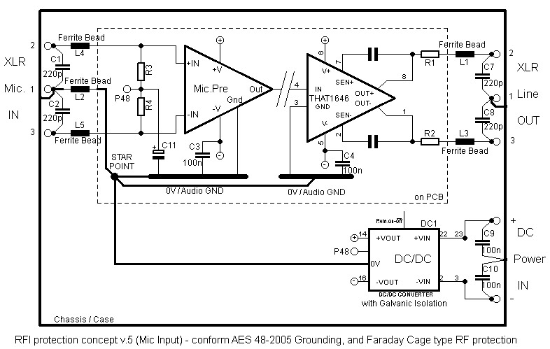
My instincts tell me that we make a huge mistake when we apply the same RFI/EMI solutions for mic or line receiver inputs fed by low impedance sources to a balanced phono input that's fed by a high impedance inductive source.
1) The input already has differential termination capacitance because the cart requires termination.
2) Any common mode capacitances you add are in parallel with the cart's differential termination.
3) Any capacitive imbalance to ground is going to wreck CMR because the source impedance is high and inductive.
4) There's series resistors (R4/R5) available to form an RC filter to prevent rectification of CM signals.
I can't argue with putting ferrite beads in series with each input but I would avoid putting CM caps on a balanced phono input.
Just don't do it.
I've actually found that the best HF CMR performance is obtained when C1/C2 are used for termination, R4/R5 are installed and C3 is linked open.
If you do have RF ingress, which I've never seen here, link C3.
My focus would be to install actual shielded cable from the 5P XLR to the board's input rather than hand-twisted pair with poor balance subject to all kinds of electrostatic interference and capacitive pickup from the higher-level portions of the board.
You're loosing sleep over the wrong thing IMHO.