Mic Preamp DC-Servo: The "backwards" way
Posted: Wed Oct 22, 2014 12:31 pm
I'm working on a slightly different DC-servo for a mic-pre using the typical instrumentation amp topology. Repeated online searches brought me here over and over again, so I decided to present my idea here.
PART 1
Below is the (simplified) "classic" input stage as basis for the discussion:
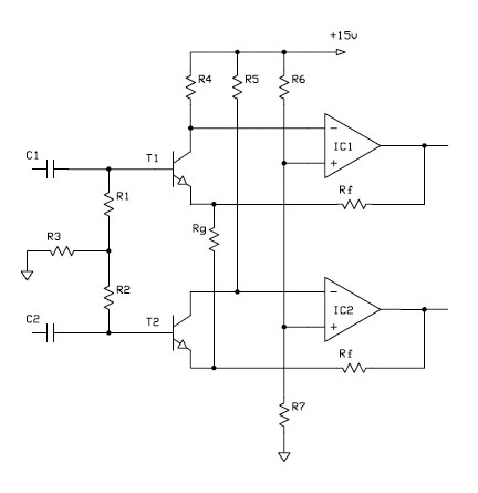
As you can see, I'm using what people here seem to call "T-bias" in order to increase the common-mode impedance and thus reduce the influence of input cap mismatch. Might even give bootstrapping (a la Whitlock) a try.
Many mic-pres I've seen that are using a DC-servo inject the correction voltage into the base of one input transistor. In order to not upset the T-bias I'm using a differential servo. Injecting the voltages into the bases seems odd, since it messes with the high(ish) common-mode impedance. The injection resistors would need to be fairly large. So I started looking for a better place to connect the servo to.
The main cause of DC offset at the output is differences in Vbe of the input transistors that lead to a DC offset across Rf which in turn gets amplified by the gain of the preamp. When looking at only the DC part (and assuming perfect components, except the transistors), the circuit shown above sets collector currents (and thus the DC operating point) by choosing the appropriate ratio between R6 and R7. Change the ratio between R6 and R7 and you get a different (common-mode) DC-offset at the output.
But we can draw the circuit like this as well:
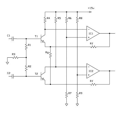
Assuming R6=R8 and R7=R9 this does basically the same (apart from slightly higher noise, since both halves now see uncorrelated resistor noise, before the single noise source was a common-mode signal). But now it's clear that we can also change the bias voltages independently. By differentially adjusting the bias voltages, the differential DC offset at the output can be changed. This also alters the collector currents for each of the input transistors (with their sum being constant, if we use a differential servo).
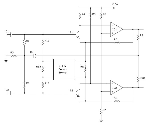
Actual implementation can be done several different ways. One could go completely overboard and build a summing circuit that sums the servo's correction voltages with a (user-setable) bias voltage. The first version I built used CCS instead of R7 and R9 with the servo altering the current. Now I have one on the bench that simply puts a 100 Ohms resistor between R7 and R9 and ground, respectively. The junction between them is used to insert the servo voltage, effectively pulling the bottom ends of R7 and R9 slightly away from ground (in opposite directions).
PART 2
Where to measure the DC offset? So far I've seen two options. There was some discussion on this forum showing them, so I'll link to that thread: viewtopic.php?f=6&t=256
In short, there is the option of monitoring the DC offset across the gain set resistor (as shown in the "Phantom Menace" AES paper) or monitoring the output.
The last method has the drawback that the servos effective frequency changes with gain. If you make it too hight, you can get interaction with the phantom blocking caps at hight gains. Make it too low, and it takes ages for the DC offset to go away at low gains (and offsets due to temperature changes might be faster than the servo can correct them). That's why I prefer the first method of monitoring the DC offset across the gain set resistor. Drawback here is that any remaining DC offset at the gain set resistor will be amplified by the amp's gain. To get rid of that just use another servo for the diff-amp / output stage (which has fixed gain, so no moving frequency of the servo).
(Actually, there is a third option which I've never seen anybody using: split Rf into two resistor and monitor offset in the middle. Depending on the split ratio you can get a mix of both versions mentioned above.)
Now for the intersting part: Why does my servo arrangement with controlling the bias voltages only work with the servo monitoring the output?
Olaf
PART 1
Below is the (simplified) "classic" input stage as basis for the discussion:
As you can see, I'm using what people here seem to call "T-bias" in order to increase the common-mode impedance and thus reduce the influence of input cap mismatch. Might even give bootstrapping (a la Whitlock) a try.
Many mic-pres I've seen that are using a DC-servo inject the correction voltage into the base of one input transistor. In order to not upset the T-bias I'm using a differential servo. Injecting the voltages into the bases seems odd, since it messes with the high(ish) common-mode impedance. The injection resistors would need to be fairly large. So I started looking for a better place to connect the servo to.
The main cause of DC offset at the output is differences in Vbe of the input transistors that lead to a DC offset across Rf which in turn gets amplified by the gain of the preamp. When looking at only the DC part (and assuming perfect components, except the transistors), the circuit shown above sets collector currents (and thus the DC operating point) by choosing the appropriate ratio between R6 and R7. Change the ratio between R6 and R7 and you get a different (common-mode) DC-offset at the output.
But we can draw the circuit like this as well:
Assuming R6=R8 and R7=R9 this does basically the same (apart from slightly higher noise, since both halves now see uncorrelated resistor noise, before the single noise source was a common-mode signal). But now it's clear that we can also change the bias voltages independently. By differentially adjusting the bias voltages, the differential DC offset at the output can be changed. This also alters the collector currents for each of the input transistors (with their sum being constant, if we use a differential servo).
Actual implementation can be done several different ways. One could go completely overboard and build a summing circuit that sums the servo's correction voltages with a (user-setable) bias voltage. The first version I built used CCS instead of R7 and R9 with the servo altering the current. Now I have one on the bench that simply puts a 100 Ohms resistor between R7 and R9 and ground, respectively. The junction between them is used to insert the servo voltage, effectively pulling the bottom ends of R7 and R9 slightly away from ground (in opposite directions).
PART 2
Where to measure the DC offset? So far I've seen two options. There was some discussion on this forum showing them, so I'll link to that thread: viewtopic.php?f=6&t=256
In short, there is the option of monitoring the DC offset across the gain set resistor (as shown in the "Phantom Menace" AES paper) or monitoring the output.
The last method has the drawback that the servos effective frequency changes with gain. If you make it too hight, you can get interaction with the phantom blocking caps at hight gains. Make it too low, and it takes ages for the DC offset to go away at low gains (and offsets due to temperature changes might be faster than the servo can correct them). That's why I prefer the first method of monitoring the DC offset across the gain set resistor. Drawback here is that any remaining DC offset at the gain set resistor will be amplified by the amp's gain. To get rid of that just use another servo for the diff-amp / output stage (which has fixed gain, so no moving frequency of the servo).
(Actually, there is a third option which I've never seen anybody using: split Rf into two resistor and monitor offset in the middle. Depending on the split ratio you can get a mix of both versions mentioned above.)
Now for the intersting part: Why does my servo arrangement with controlling the bias voltages only work with the servo monitoring the output?
Olaf