Page 9 of 10
Re: modified GFCI
Posted: Mon May 23, 2016 5:34 am
by mediatechnology
So what's the next step? UL submission for testing?
Everyone needs one of these.
Re: modified GFCI
Posted: Mon May 23, 2016 9:50 am
by JR.
mediatechnology wrote:So what's the next step? UL submission for testing?
I will make a few more attempts to secure a partner to make and sell these, but if unsuccessful I will approach UL myself. I am not enthusiastic about the cost of filing with UL. I had to pay $400 just to buy a copy of the UL spec for these so I could read it. I am too old and tired to start another company.
Everyone needs one of these.
Maybe not everybody, but the ones sold now are actually dangerous.
JR
Re: modified GFCI
Posted: Mon May 23, 2016 12:11 pm
by mediatechnology
Re: modified GFCI
Posted: Mon May 23, 2016 12:17 pm
by JR.
I got having business partners and investors out of my system back in the early 80s (Loft).
I literally do not want to build another business from scratch, but I do want to see this product in the market. I would give it to the right partner. But business partners wouldn't value it for free. So I need to do the dance.
JR
Re: modified GFCI
Posted: Mon May 23, 2016 4:27 pm
by JR.
Oh well it is time for me to get more aggressive... I called one company earlier today and the switchboard wouldn't connect me to the product manager for the line of products my tester would be in, instead he said they have a woman who reviews new idea submissions and he's connect me... straight to voice mail without even a name... I know how this works. So I submitted a quality control complaint about the new product ideas review... we'll see if anybody reads that arghhhhhhhhhh

I bit the bullet and submitted a RFQ with UL directly to start an approval. I have contacted other testing labs for quote but they decline to test UL S1436, the spec that applies to outlet testers.
I might go outlaw on this. I know the product is safe as I designed it (>550M insulation resistance to the touch probe), but UL approval would be better. I can use the money I didn't waste getting a patent.

JR
Re: modified GFCI
Posted: Mon May 30, 2016 11:47 am
by JR.
I heard back from UL and spoke on the phone with a clerical type.
Now I am waiting for him to set up a conference phone call with the local UL rep and some senior engineering types.
They initially suggested it should be classified/tested as laboratory equipment while I believe it should be consumer. It was pointless to debate with the clerk who admitted no technical chops.
At least my initial contact sounded receptive to classifying the already approved by UL, plug housing as an approved sub assembly to simplify and reduce my testing cost. The UL spec involves a lot of physical/mechanical testing for the plug blades and housing material that seems redundant for an already approved part.
I expected the conference call to happen a little quicker. It's been over a week since the last call.
Oh well no real hurry, this will cost me mo money.
JR
Re: modified GFCI
Posted: Wed Jun 01, 2016 10:24 pm
by emrr
Good luck! I hope you can get it out there properly.
Re: modified GFCI
Posted: Wed Sep 21, 2016 12:14 pm
by JR.
I am swiftly losing interest in this project (I'm too old to start another company) and would be unlikely to break even after the UL agency testing expense.
======
UL still hasn't answered my last question (about what device they use for insulation resistance testing). The spec calls for using a "magnetomegometer" with 500V open circuit voltage. Since i can not find any such type of test equipment in google I asked for clarification. FWIW a "Megnetometer" is a device for measure magnetic fields (flux) so it seems a magneto(meg)ometer would be a higher sensitivity flux meter, and still would not have an open circuit voltage. A "mego(hm)meter" is a common high resistance ohm meter that could have a 500V open circuit voltage. OTOH a magneto(-)megometer (hyphen added by me) sounds like a real thing, a hand crank magneto to provide a megohmmeter's voltage source.
Since it has been weeks since I asked them with no answer, I am losing interest. I do not want to submit based on my best guess.
I am ready to abandon making and selling these myself. Also I have had no success developing a constructive partnership with an existing manufacturer. As promised I am publishing the technology so any and all can use it for free. I never did this for money.
 http://www.johnhroberts.com/OD1.htm
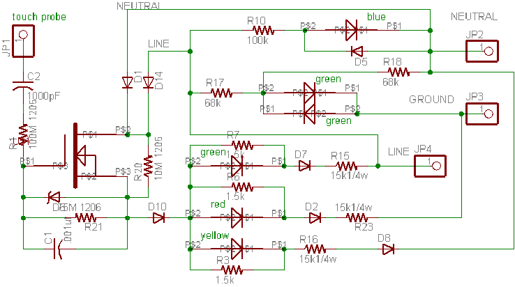
I have published a written description of how this works (at link above). Since this is a design forum I invite all who see this to check out my circuit description there and tell me if there are still parts of the circuit that are not clear. Most of this circuit is obvious but some parts of it are pretty obscure, especially how the local reference actually works.. I didn't figure it out for several months into the development process. There is a difference between making something that works, and understanding how it works. :-\ Some of what looks like extra parts was done to meet or anticipate the UL spec.
Please share this with anyone who might have interest. I expect the technology has multiple human safety applications beyond just outlet testers.
JR
PS: This new OD-1 web page is a work in process and I will continue to add more information like a comprehensive BOM, etc.
Re: modified GFCI
Posted: Fri Sep 23, 2016 5:17 pm
by mediatechnology
Thanks for sharing this JR.
I need to study the circuit description because there's a lot going on under the surface as is typical with your designs.
I still get lost in some places of the TS-1.
Re: modified GFCI
Posted: Sat Sep 24, 2016 9:58 am
by JR.
mediatechnology wrote:Thanks for sharing this JR.
I need to study the circuit description because there's a lot going on under the surface as is typical with your designs.
I still get lost in some places of the TS-1.
I can get lost looking at the TS-1 and I designed it
30+ years ago.
This is half obvious (LED indications with diode current steering) and half magic (input buffer). It took me almost a year to understand (I think) how it works.
JR