It had occurred to me some time ago, and I just remembered, (thank you Hans) that R13-R18 contribute additional differential mode noise not present in either the original prototype or sim.
Without first dealing with measurement hum I couldn't really look at it.
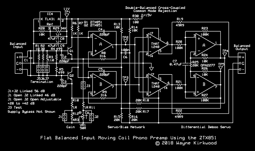
In the original circuit, a single voltage divider is used to set Ic for both halves.
The noise of the divider network is presented in common mode and rejected.
The circuit with the updated servo uses two dividers in a bridge configuration.
R17 and R18 inject servo correction to the bridge.
A differential noise voltage appears across C6 and the non-inverting inputs of op amps A and B of the first stage.
The Thevenin equivalent of the bridge is 5KΩ per leg.
Those resistors are not modeled (I think) or are in first set of measurements.
My gut tells me the servo op amp noise, in comparison to the aforementioned resistors, is
de minimus.
The solution (I suppose) is to make C6 the dominate servo pole and C7 one much higher in frequency.
C7 still provides a passive input pole to relax AC requirements of the servo amp.
C6, if made significantly larger than 100nF, then serves double-duty to filter differential noise and provide integration.
(Since servos produce a derived, subtracted, HP response we don't want to get cute and introduce a second-order response that would peak.)
The second thing I'd do is insert two low-value (47-100Ω?) resistors in series between Q1's collector and op amp A's inverting input. (And a second between Q2 op amp B.)
The purpose of that, I believe, will allow a reduction in the value of C4 and C5.
My unscientific guess is that this will better-isolate Q1 and Q2's output capacitance from op amps A and B inverting node.
When I'm curious enough to fire up the Protoboard again I'll report back.