terkio wrote: ↑Wed Feb 27, 2019 8:54 am
I think the various ways to inject servo correction do not make much difference in the case of a fixed gain preamp, it's only a matter of convenience.
In the case of variable gain, that is an all different story and this is an excellent paper showing the issues.
http://www.thatcorp.com/datashts/AES919 ... ifiers.pdf
I looked at injection at the emitters. It works great to achieve
servo action independant of gain. This is why: A key point of the "Cohen topology" is that Ic is constant thanks to the op amps that enforce this to be. Vcb is constant too. The results are that Ie is constant, Ve is constant. So when injecting a current at the emitter, it can only flow into Rf the feedback resistance, regardless of the preamp gain. Furthermore, current injection is accurately done, simply with a resistor from the servo since Ve is at a constant voltage and near zero.
I checked with LTSpice, it does work as said. The current injection all flows into Rf with near no other effect in the preamp. The servo action does not depend of the preamp gain.
Wether one wants servo action independant of gain versus dependant of gain is another story. We have means to cleanly achieve one or the other.
I agree on all points.
Having fc fixed in a fixed gain preamp really doesn't help much since once you know gain you can move fc if you want to keep it constant.
If gain can be varied by 20 dB, and you're using servo fc as a first-order derived high-pass, then it might matter since the HP fc would move by a 10:1 ratio.
The derived first-order high-pass might be useful for simple warp reduction for instance.
This is a point that I've been wanting to make for a long time and it is a point the THAT paper makes in a different way:
"A servo, which is a low-pass filter, produces a derived, subtracted, high-pass response."
This is why second-order servos peak and why inadvertent second-order servos illustrated in the THAT paper also peak.
An "analog" is the derived response of a second-order, uncorrected, elliptic equalizer.
viewtopic.php?f=6&t=828
I've written an xls calculator based on Gary's half-circuit equations and have used them here and elsewhere.
Not sure I ever posted it.
Injection at the emitters is something I've tried and used with success.
For some applications, such as digital gain control, current flow back into the feedback resistors may be problematic.
What I did was split the emitter current sinks in this circuit.
I then applied a common mode correction signal and a differential one.
See:
http://www.thatcorp.com/datashts/dn109.pdf
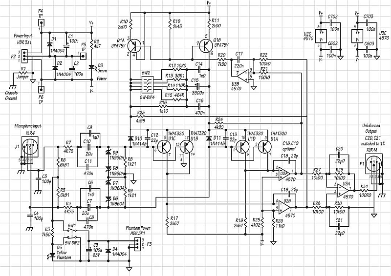
The bases of Q1A and Q1B can be considered summing nodes.
Splitting the base connections and summing a shared common mode correction into both bases along with differential correction allows both transistors to control input stage Ie. (4 resistors 2X/transistor base.)
The advantage of controlling Ie or Ic (Vc) over base correction is that low impedance at DC sources don't differentially shunt the base currents used for correction. (Think ribbon mic or MC phono pickup directly to bases.)
In the MC preamp correction of Vc or Ie are both viable options.
Since the op amps are supplying Ie we're not concerned about current in Rfa or Rfb.
Thanks for doing the sims.
I've "simulated" all three in 3D on the bench so its good to know sims do relate in some way to reality.