Dual Class-A Line and Headphone Output Board Construction Information
Posted: Wed Feb 08, 2012 3:44 pm
Note: This board is no longer available and has been replaced by the Dual Class-A II. http://www.proaudiodesignforum.com/foru ... ?f=7&t=825
Update 1/5/2015:
Apparently not all BD139/BD140s are insulated. The Fairchild parts shown in the BOM do not require insulators. Oddly the datasheet makes no mention of this nor does the packaging datasheet.
ST BD139s and BD140s do require insulators.
Update 9/6/2014:
There's now a Mouser Project Manager bill of materials for the Dual Class-A. The links are provided below.
These lists are not directly editable but you can "order" the project to move it to your shopping cart, then save the cart as a project to allow editing.
Or, you can simply edit the cart at the time of ordering.
The following link is for the "headphone amp" version using a DRV134.
It has 33R build-out resistors (which can be as low as 0R or as high as you wish) and THAT1240 "OdB" line receivers.
Headphone Amp Project Manager link: https://www.mouser.com/ProjectManager/P ... fc004530aa (material cost as of 9/6/2014 in USD $64.96)
This link is for the "line driver" version also using a DRV134.
It has 47R build-out resistors and THAT1246 "-6dB" line receivers.
Line Driver Project Manager link: https://www.mouser.com/ProjectManager/P ... 527853a78f (material cost as of 9/6/2014 in USD $64.96)
The heatsink shown in both Project Manager BOMs are the 5 degC/W CTS.
This larger heatsink is normally stocked by both Mouser and DIgi-Key.
The 9 degC/W heatsink (shown in the photo below) are in the Mouser and Digi-Key catalogs but are not normally stocked.
There is a discussion about the CTS heatsinks further in this post which show the part numbers for both models.
You can easily make your own heatsink however from a piece of extrusion or salvage one from a blown PC power supply.
The smaller CTS heatsink, with an output stage idle current of 85 mA, is more than adequate having a typical temperature of 125-130 deg F.
Note as of 9/6/14 that I have not received my test order to verify the accuracy of the lists so please manually check the list before ordering.
Production DRV134 Build
Dual Class-A Output using a Current-boosted DRV134.
Brief Description
The Dual Class-A Output uses the THAT1646 or DRV134 with discrete BD139/BD140 outputs and a THAT1240 or THAT1246 for balanced input.
A second BD139 serves as a Vbe multiplier and provides thermal feedback.
If desired, the Dual Class-A can be used fully direct-coupled with low output offset typ <5mV.
Gain is unity or -6dB depending upon the application and choice of line receiver.
A low impedance open-loop output (<2 Ohms) permits driving capacitive loads either with or without build-out resistance.
Inputs can be paralleled or cross-coupled via jumper selection.
Phoenix connectors are provided for input, output, power and optional level controls for headphone use.
The Dual Class-A board can be used as
1) A stereo headphone amp.
2) Dual single-ended class-A line output.
3) Fully-balanced line output with cross-coupled differential input.
4) A high-current line "re-balancer."
5) Dual single-ended or differential transformer driver.
6) Dual output distribution amp.
7) Parallel operation (without external ballast resistors) for double output current.
8) Passive EQ network driver. (Pultec)
9) Control Room monitor driver.
10) A few more things we haven't thought of yet.
I'm going to be using a set of these to buffer the sound card output to drive stuff on the bench and another set as a precision headphone amp.
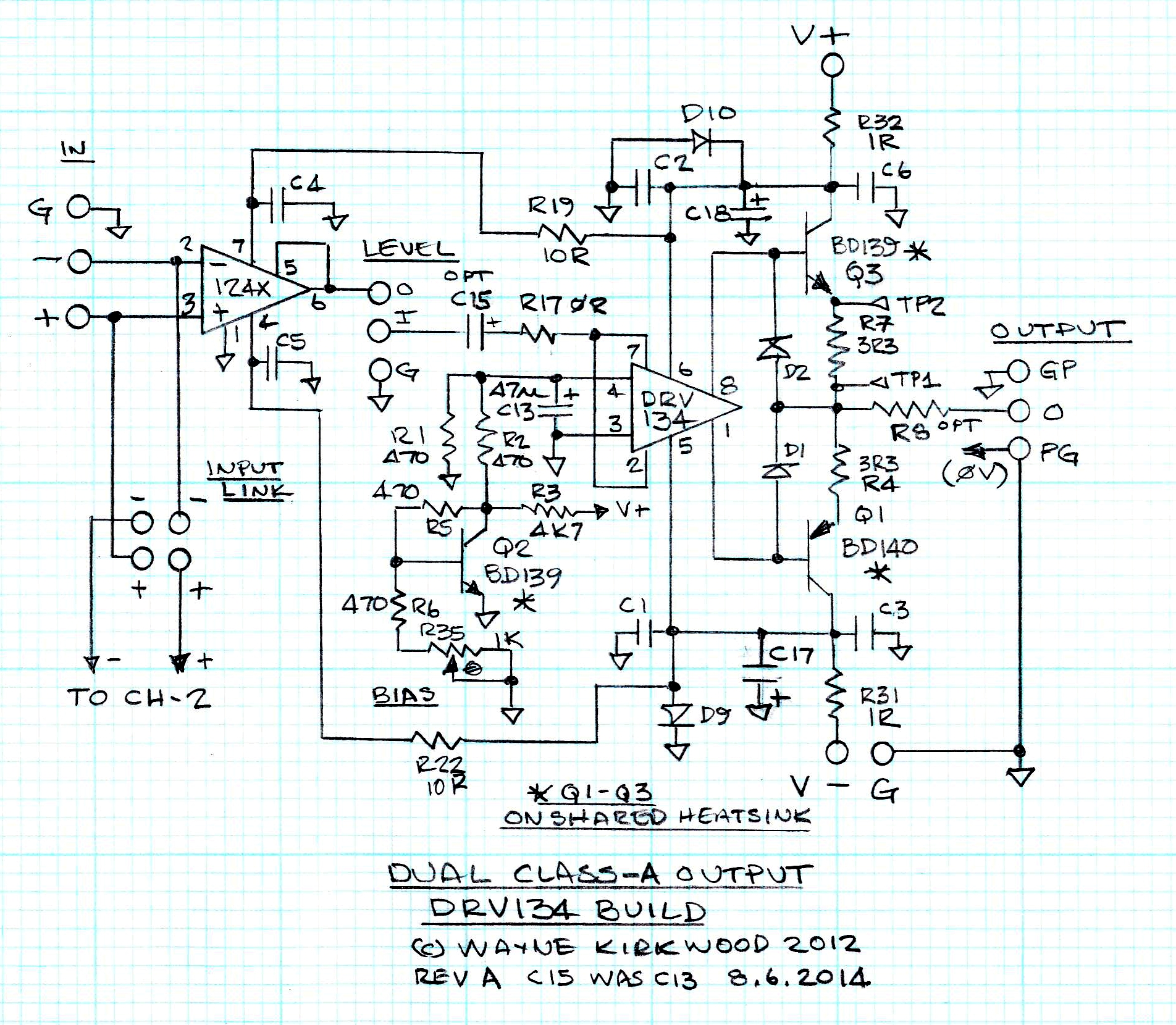
Schematic of the DRV134 build
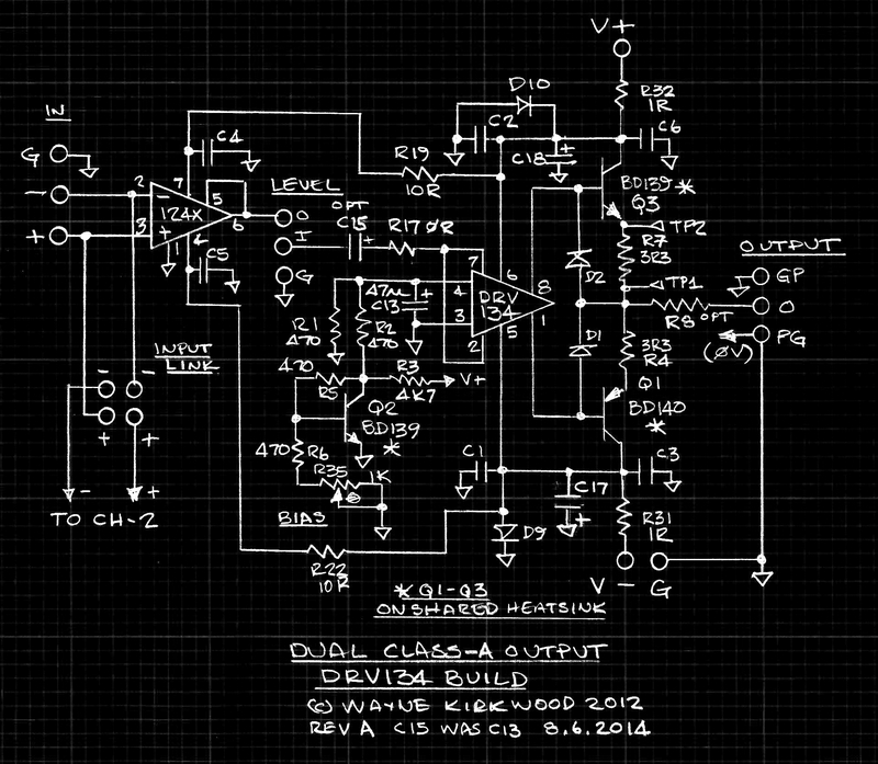
Dual Class-A Output schematic using a Current-boosted DRV134
Large schematic suitable for printing: http://www.ka-electronics.com/images/jp ... _Large.JPG
Dual Class-A Output Circuit Description
Input for the dual Class-A is received by a "0dB" gain THAT1240 (INA134) or "-6dB" gain THAT1246 (INA137). The choice of line receiver gain is up to the user but generally-speaking 0 dB parts are used for headphone amplifier applications or when the board is used as a dual single-ended output. -6dB gain is the best choice for fully-balanced outputs when the inputs are cross-coupled because it provides overall unity gain input to output.
Input links allow (1) dual operation, (2) parallel input in which both outputs are driven in the same polarity, or (3) cross-coupled which drives the outputs in push-pull to provide a fully-balanced differential output.
A Phoenix terminal block permits level trim or headphone volume control to be inserted prior to the output stage.
The dual Class-A output does not provide gain. For applications as a headphone amplifier with professional line levels or with consumer level ("-10") equipment driving moderately sensitive headphones, gain is not usually required. In the rare application in which gain is required, an external stage providing both gain and volume control can be inserted after the input stage.
The dual Class-A is fully DC-coupled with the exception of C13 (left channel). C13 is optional for headphone applications where there might be concern about having DC in the wiper of the potentiometer. The bias current of the THAT1646 or DRV134 is satisfied internally but can return through the wiper creating excess noise. In practice several boards have been built without C13 and have been quiet. R17 (0R) exists only to provide a PC board jumper.
The THAT1646 or DRV134 are used in the dual Class-A unconventionally to provide "common mode drive" and a differential Vbe bias voltage for the output stage consisting of Q1 and Q3.
Conventional applications of the THAT1646 or DRV134 as a balanced line driver have pin 4 driven by input and pins 2 and 7 used to provide common mode feedback and ground sensing.
In the dual Class-A circuit, the DRV134 pin 4, the "differential" input, is used to provide a Vbe reference for the output devices that is "voltage mirrored" around the input signal appearing on pins 2 and 7. If the input is held at ground, the Vbe reference voltage appearing on pin 4 appears as +Vbe on pin 8 and -Vbe on pin 1. If +1 volt is applied to pins 2 and 7, then the output on pin 8 is +1V + Vbe and on pin 1 +1V - Vbe. (Note: The THAT1646 has a differential gain of 2, the DRV134 in this configuration a gain of 4. The DRV134 requires R1 and R2 to provide a Vbe/2 reference.) The "voltage mirror" is actually a Vbe or bias mirror.
Q2, a BD139 and an identical device to NPN output Q3, provides a temperature-dependent Vbe reference to set output idle current and provide thermal feedback for temperature regulation. Q2, which has identical geometry to the output devices it measures and a mounting hole, is located between output devices Q1 and Q3 on the heat sink. R3 provides a current source for Q2. R5, R6 and trim pot R35 set the output stage idle current and create Vbe multiplication. C13 provides noise filtering and turn-on delay. When the THAT1646 is used, R1 is not installed and R2 is 0R. The DRV134, when configured for common mode drive, has a differential gain of 4. R1 and R2 scale the collector voltage of Q2 by 1/2 when a DRV134 is used. The voltage at the collector of Q2 appears on pin 8 and its inverted "Vbe mirror" image on pin 1.
Q1 and Q3 form an open loop output stage. D1 and D2 provide reverse Vbe protection for Q1 and Q3. R4 and R7 provide emitter degeneration and provide ballasting when both channels' outputs are paralleled.
R35 sets the output stage current which is measured indirectly as a voltage at TP1 and TP2. Currents from 50 mA to 85 mA are typically used to maintain heavy class-A operation. 50 mA produces 165 mV; 85 mA, 280 mV.
R8 is an optional build-out resistor and is not essential to maintain stability with highly-capacitive loads. The selection of R8's value depends on a number of factors including short-circuit protection capability and optimum matching to the load. Generally, for headphone applications, R8 can range from 0 to 33 Ohms or more. For balanced line driving applications, which are usually terminated in 100-120 Ohm shielded twisted pair, 45-50 Ohms per leg provides maximally-flat transient response, reduced DIM distortion and reduced peak current requirements.
The output connector for each channel has two ground connections. The "GP" (ground plane) connections may be used to connect cable shields. The "PG" (power ground) connection has a dedicated return trace to the power connector ground and should be used for headphone driving where there is significant current in the return.
D9 and D10 provide reverse polarity protection. R31 and R32, which are "defined interruption" (fusible) resistors, serve to limit current in the event of reverse polarity. In applications where R8 is made low, e.g. 0 Ohms, the builder might want to consider making R31 and R32 larger to provide short circuit protection. C17 and C18 provide bulk bypass capacitance. R19, R22 and C1-C6 (100 nF) provide local bypass.
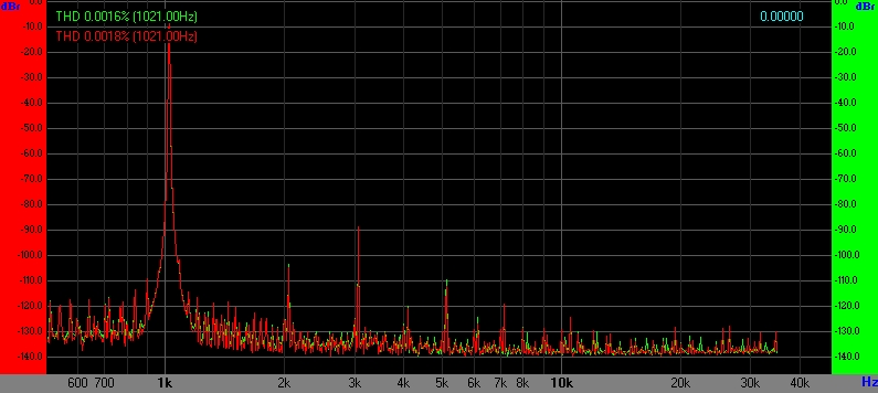
Distortion performance
30 Ohm load at 100 mW. Rbuildout = 0R.
Green is output, Red generator monitor.
The driver adds ~ 0.0017% THD.

Dual Class-A Headphone Amplifier with 30 Ohm load at 100 mW.
600 Ohm load, single-ended, +20 dBu. Rbuildout 0R.
Green is output, Red generator monitor.
Note that the output THD is essentially identical to the generator.
To fully see what the THD is a null test is required.
The driver subtracts ~ 0.0002% THD.
Dual Class-A Line Driver with 600 Ohm load at +20 dBu.
Dual Class-A DRV134 Bill of Materials
(Mouser part numbers shown.)
4 IC Socket, 8P
4 Diode, 1N4148
4 Diode, 1N4004
8 Resistor, 470R 0.25W (475R in 1%)
2 Resistor, 4K7 0.25W (4K75 in 1%)
4 Resistor, 10R 0.25W
2 Resistor, 0R* 0.25W MF Jumper, 71-FRJ-50-0
4 Resistor, 1R* 1W MF, 594-5073NW1R000J
4 Resistor, 3R3 1W MF, 594-5073NW3R300J
2 Resistor, 47R* 1W MF, 594-5073NW47R00J
12 Capacitor, 100nF 100V, 581-SR201C104KAR
2 Capacitor, 47uF 35V, 647-UVR1V470MDD
4 Capacitor, 220uF 25V, 647-UVR1E221MPD
1 Header, 4 Pos, 538-90131-0122
1 Terminal Block, 3 Pos, 5.08mm, 651-1715734
6 Terminal Block, 3 Pos, 2.54mm, 651-1725669
4 Transistor BD139-16, (160 Hfe) 512-BD13916S
2 Transistor BD140-16. (160 Hfe) 512-BD14016S
6 each 4-40 x 1/2" screw, lockwasher and nut.
2 Trim Pot, 1K, 15T, 594-64W102
2 Line Driver IC, DRV134PA
2 Line Receiver IC, THAT124X or INA13X. (Depends on gain.)
Note: C15, C16, C21-C24, D5-D8, R18, R20, R21, R23, R25, R27, R28, R30, IC3-IC6 not used.*
Heatsinks:
Stocked heatsink:
Qty 2 Heatsink, CTS 7-342-2PP-BA, 5 degC/W, Mouser 774-73422PPBA, Digi-Key 294-1086-ND
The smaller heatsink, shown in the prototype photo and bottom one in the image, is not normally stocked:
Qty 2 Heatsink, CTS 7-342-1PP-BA, 10 degC/W, Mouser 774-73421PPBA, Digi-Key 294-1085-ND
Digi-Key and Mouser sometimes have the smaller CTS 7-342-1PP-BA left-over from customer orders.
It always pays to check.
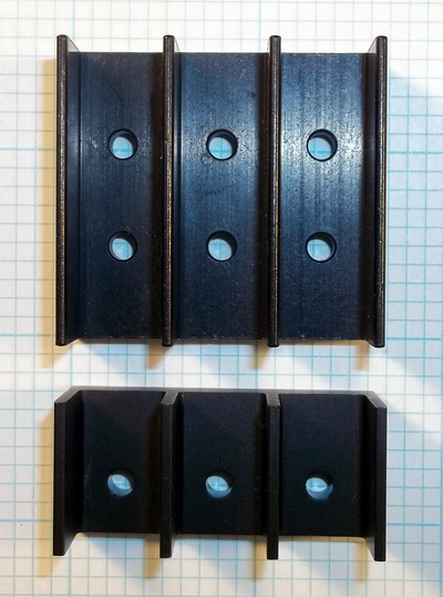
CTS Heatsinks PN 7-342-2PP-BA (top) and PN 7-342-1PP-BA (bottom) on 0.1" grid
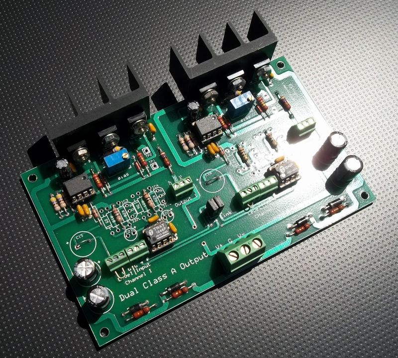
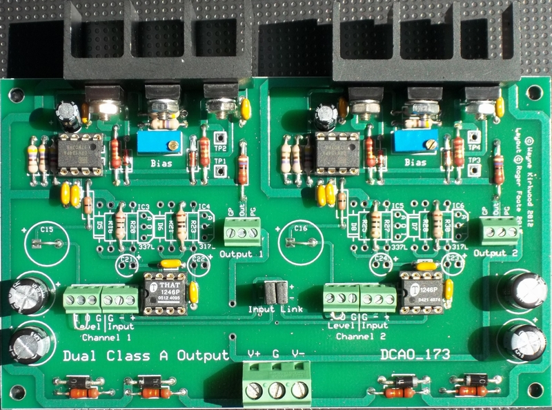
A picture of the stuffed Dual Class-A board
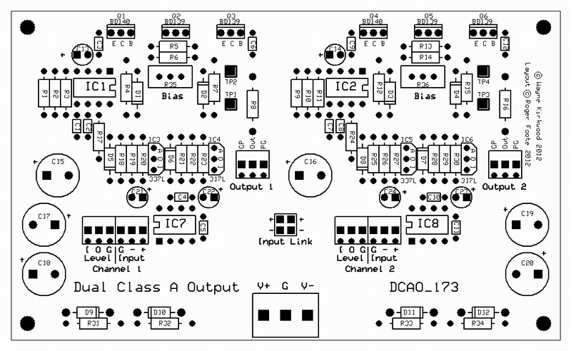
Dual Class-A board stuffing diagram
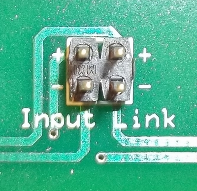
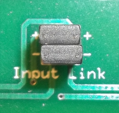
Input Jumper Configurations:
Dual Class-A Input jumper settings for independent stereo operation providing two single-ended outputs.
Applications include headphone amps and dual transformer drivers.
Dual Class-A Input jumper settings for independent stereo operation providing two single-ended outputs.
Dual Class-A Input jumper settings providing differential fully-balanced push-pull output with a differential cross-coupled input stage.
Applications include balanced line and balanced transformer drivers.
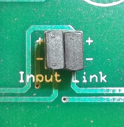
Dual Class-A Input jumper settings providing a differential push-pull output with a differential cross-coupled input stage.
Dual Class-A Input jumper settings providing outputs driven with the same polarity.
The dual Class-A outputs can be paralleled without external ballasting resistors.
Applications include distribution amps, high-current headphone outputs with double the load current, high-current line drivers, 150 Ohm (or less) transformer drive and passive EQ network driver.
Dual Class-A Input jumper settings providing outputs driven with the same polarity.
Update 1/5/2015:
Apparently not all BD139/BD140s are insulated. The Fairchild parts shown in the BOM do not require insulators. Oddly the datasheet makes no mention of this nor does the packaging datasheet.
ST BD139s and BD140s do require insulators.
Update 9/6/2014:
There's now a Mouser Project Manager bill of materials for the Dual Class-A. The links are provided below.
These lists are not directly editable but you can "order" the project to move it to your shopping cart, then save the cart as a project to allow editing.
Or, you can simply edit the cart at the time of ordering.
The following link is for the "headphone amp" version using a DRV134.
It has 33R build-out resistors (which can be as low as 0R or as high as you wish) and THAT1240 "OdB" line receivers.
Headphone Amp Project Manager link: https://www.mouser.com/ProjectManager/P ... fc004530aa (material cost as of 9/6/2014 in USD $64.96)
This link is for the "line driver" version also using a DRV134.
It has 47R build-out resistors and THAT1246 "-6dB" line receivers.
Line Driver Project Manager link: https://www.mouser.com/ProjectManager/P ... 527853a78f (material cost as of 9/6/2014 in USD $64.96)
The heatsink shown in both Project Manager BOMs are the 5 degC/W CTS.
This larger heatsink is normally stocked by both Mouser and DIgi-Key.
The 9 degC/W heatsink (shown in the photo below) are in the Mouser and Digi-Key catalogs but are not normally stocked.
There is a discussion about the CTS heatsinks further in this post which show the part numbers for both models.
You can easily make your own heatsink however from a piece of extrusion or salvage one from a blown PC power supply.
The smaller CTS heatsink, with an output stage idle current of 85 mA, is more than adequate having a typical temperature of 125-130 deg F.
Note as of 9/6/14 that I have not received my test order to verify the accuracy of the lists so please manually check the list before ordering.
Production DRV134 Build
Dual Class-A Output using a Current-boosted DRV134.
Brief Description
The Dual Class-A Output uses the THAT1646 or DRV134 with discrete BD139/BD140 outputs and a THAT1240 or THAT1246 for balanced input.
A second BD139 serves as a Vbe multiplier and provides thermal feedback.
If desired, the Dual Class-A can be used fully direct-coupled with low output offset typ <5mV.
Gain is unity or -6dB depending upon the application and choice of line receiver.
A low impedance open-loop output (<2 Ohms) permits driving capacitive loads either with or without build-out resistance.
Inputs can be paralleled or cross-coupled via jumper selection.
Phoenix connectors are provided for input, output, power and optional level controls for headphone use.
The Dual Class-A board can be used as
1) A stereo headphone amp.
2) Dual single-ended class-A line output.
3) Fully-balanced line output with cross-coupled differential input.
4) A high-current line "re-balancer."
5) Dual single-ended or differential transformer driver.
6) Dual output distribution amp.
7) Parallel operation (without external ballast resistors) for double output current.
8) Passive EQ network driver. (Pultec)
9) Control Room monitor driver.
10) A few more things we haven't thought of yet.
I'm going to be using a set of these to buffer the sound card output to drive stuff on the bench and another set as a precision headphone amp.
Schematic of the DRV134 build
Dual Class-A Output schematic using a Current-boosted DRV134
Large schematic suitable for printing: http://www.ka-electronics.com/images/jp ... _Large.JPG
Dual Class-A Output Circuit Description
Input for the dual Class-A is received by a "0dB" gain THAT1240 (INA134) or "-6dB" gain THAT1246 (INA137). The choice of line receiver gain is up to the user but generally-speaking 0 dB parts are used for headphone amplifier applications or when the board is used as a dual single-ended output. -6dB gain is the best choice for fully-balanced outputs when the inputs are cross-coupled because it provides overall unity gain input to output.
Input links allow (1) dual operation, (2) parallel input in which both outputs are driven in the same polarity, or (3) cross-coupled which drives the outputs in push-pull to provide a fully-balanced differential output.
A Phoenix terminal block permits level trim or headphone volume control to be inserted prior to the output stage.
The dual Class-A output does not provide gain. For applications as a headphone amplifier with professional line levels or with consumer level ("-10") equipment driving moderately sensitive headphones, gain is not usually required. In the rare application in which gain is required, an external stage providing both gain and volume control can be inserted after the input stage.
The dual Class-A is fully DC-coupled with the exception of C13 (left channel). C13 is optional for headphone applications where there might be concern about having DC in the wiper of the potentiometer. The bias current of the THAT1646 or DRV134 is satisfied internally but can return through the wiper creating excess noise. In practice several boards have been built without C13 and have been quiet. R17 (0R) exists only to provide a PC board jumper.
The THAT1646 or DRV134 are used in the dual Class-A unconventionally to provide "common mode drive" and a differential Vbe bias voltage for the output stage consisting of Q1 and Q3.
Conventional applications of the THAT1646 or DRV134 as a balanced line driver have pin 4 driven by input and pins 2 and 7 used to provide common mode feedback and ground sensing.
In the dual Class-A circuit, the DRV134 pin 4, the "differential" input, is used to provide a Vbe reference for the output devices that is "voltage mirrored" around the input signal appearing on pins 2 and 7. If the input is held at ground, the Vbe reference voltage appearing on pin 4 appears as +Vbe on pin 8 and -Vbe on pin 1. If +1 volt is applied to pins 2 and 7, then the output on pin 8 is +1V + Vbe and on pin 1 +1V - Vbe. (Note: The THAT1646 has a differential gain of 2, the DRV134 in this configuration a gain of 4. The DRV134 requires R1 and R2 to provide a Vbe/2 reference.) The "voltage mirror" is actually a Vbe or bias mirror.
Q2, a BD139 and an identical device to NPN output Q3, provides a temperature-dependent Vbe reference to set output idle current and provide thermal feedback for temperature regulation. Q2, which has identical geometry to the output devices it measures and a mounting hole, is located between output devices Q1 and Q3 on the heat sink. R3 provides a current source for Q2. R5, R6 and trim pot R35 set the output stage idle current and create Vbe multiplication. C13 provides noise filtering and turn-on delay. When the THAT1646 is used, R1 is not installed and R2 is 0R. The DRV134, when configured for common mode drive, has a differential gain of 4. R1 and R2 scale the collector voltage of Q2 by 1/2 when a DRV134 is used. The voltage at the collector of Q2 appears on pin 8 and its inverted "Vbe mirror" image on pin 1.
Q1 and Q3 form an open loop output stage. D1 and D2 provide reverse Vbe protection for Q1 and Q3. R4 and R7 provide emitter degeneration and provide ballasting when both channels' outputs are paralleled.
R35 sets the output stage current which is measured indirectly as a voltage at TP1 and TP2. Currents from 50 mA to 85 mA are typically used to maintain heavy class-A operation. 50 mA produces 165 mV; 85 mA, 280 mV.
R8 is an optional build-out resistor and is not essential to maintain stability with highly-capacitive loads. The selection of R8's value depends on a number of factors including short-circuit protection capability and optimum matching to the load. Generally, for headphone applications, R8 can range from 0 to 33 Ohms or more. For balanced line driving applications, which are usually terminated in 100-120 Ohm shielded twisted pair, 45-50 Ohms per leg provides maximally-flat transient response, reduced DIM distortion and reduced peak current requirements.
The output connector for each channel has two ground connections. The "GP" (ground plane) connections may be used to connect cable shields. The "PG" (power ground) connection has a dedicated return trace to the power connector ground and should be used for headphone driving where there is significant current in the return.
D9 and D10 provide reverse polarity protection. R31 and R32, which are "defined interruption" (fusible) resistors, serve to limit current in the event of reverse polarity. In applications where R8 is made low, e.g. 0 Ohms, the builder might want to consider making R31 and R32 larger to provide short circuit protection. C17 and C18 provide bulk bypass capacitance. R19, R22 and C1-C6 (100 nF) provide local bypass.
Distortion performance
30 Ohm load at 100 mW. Rbuildout = 0R.
Green is output, Red generator monitor.
The driver adds ~ 0.0017% THD.
Dual Class-A Headphone Amplifier with 30 Ohm load at 100 mW.
600 Ohm load, single-ended, +20 dBu. Rbuildout 0R.
Green is output, Red generator monitor.
Note that the output THD is essentially identical to the generator.
To fully see what the THD is a null test is required.
The driver subtracts ~ 0.0002% THD.
Dual Class-A Line Driver with 600 Ohm load at +20 dBu.
Dual Class-A DRV134 Bill of Materials
(Mouser part numbers shown.)
4 IC Socket, 8P
4 Diode, 1N4148
4 Diode, 1N4004
8 Resistor, 470R 0.25W (475R in 1%)
2 Resistor, 4K7 0.25W (4K75 in 1%)
4 Resistor, 10R 0.25W
2 Resistor, 0R* 0.25W MF Jumper, 71-FRJ-50-0
4 Resistor, 1R* 1W MF, 594-5073NW1R000J
4 Resistor, 3R3 1W MF, 594-5073NW3R300J
2 Resistor, 47R* 1W MF, 594-5073NW47R00J
12 Capacitor, 100nF 100V, 581-SR201C104KAR
2 Capacitor, 47uF 35V, 647-UVR1V470MDD
4 Capacitor, 220uF 25V, 647-UVR1E221MPD
1 Header, 4 Pos, 538-90131-0122
1 Terminal Block, 3 Pos, 5.08mm, 651-1715734
6 Terminal Block, 3 Pos, 2.54mm, 651-1725669
4 Transistor BD139-16, (160 Hfe) 512-BD13916S
2 Transistor BD140-16. (160 Hfe) 512-BD14016S
6 each 4-40 x 1/2" screw, lockwasher and nut.
2 Trim Pot, 1K, 15T, 594-64W102
2 Line Driver IC, DRV134PA
2 Line Receiver IC, THAT124X or INA13X. (Depends on gain.)
Note: C15, C16, C21-C24, D5-D8, R18, R20, R21, R23, R25, R27, R28, R30, IC3-IC6 not used.*
Heatsinks:
Stocked heatsink:
Qty 2 Heatsink, CTS 7-342-2PP-BA, 5 degC/W, Mouser 774-73422PPBA, Digi-Key 294-1086-ND
The smaller heatsink, shown in the prototype photo and bottom one in the image, is not normally stocked:
Qty 2 Heatsink, CTS 7-342-1PP-BA, 10 degC/W, Mouser 774-73421PPBA, Digi-Key 294-1085-ND
Digi-Key and Mouser sometimes have the smaller CTS 7-342-1PP-BA left-over from customer orders.
It always pays to check.
CTS Heatsinks PN 7-342-2PP-BA (top) and PN 7-342-1PP-BA (bottom) on 0.1" grid
A picture of the stuffed Dual Class-A board
Dual Class-A board stuffing diagram
Input Jumper Configurations:
Dual Class-A Input jumper settings for independent stereo operation providing two single-ended outputs.
Applications include headphone amps and dual transformer drivers.
Dual Class-A Input jumper settings for independent stereo operation providing two single-ended outputs.
Dual Class-A Input jumper settings providing differential fully-balanced push-pull output with a differential cross-coupled input stage.
Applications include balanced line and balanced transformer drivers.
Dual Class-A Input jumper settings providing a differential push-pull output with a differential cross-coupled input stage.
Dual Class-A Input jumper settings providing outputs driven with the same polarity.
The dual Class-A outputs can be paralleled without external ballasting resistors.
Applications include distribution amps, high-current headphone outputs with double the load current, high-current line drivers, 150 Ohm (or less) transformer drive and passive EQ network driver.
Dual Class-A Input jumper settings providing outputs driven with the same polarity.