Page 2 of 14
Re: Dual Class-A Line and Headphone Output Board
Posted: Sat Apr 21, 2012 11:15 am
by mediatechnology
OK, cool. I'll be in touch.
Re: Dual Class-A Line and Headphone Output Board
Posted: Wed Apr 25, 2012 12:24 pm
by mediatechnology
OK, I've put in a production run that should be here in about two weeks. Looks like I've got some documentation to do....
Re: Dual Class-A Line and Headphone Output Board
Posted: Fri May 04, 2012 4:23 pm
by mediatechnology
Roger - I arrived at 85 mA Iq for headphone amp use. 50 mA seems quite reasonable for transformer drive.
Boards will be in next week - the vendor "underpromised and over-delivered" having them here in about half the quoted time.
Re: Dual Class-A Line and Headphone Output Board
Posted: Sat May 05, 2012 3:39 am
by tmuikku
I'm following with great interest

Re: Dual Class-A Line and Headphone Output Board
Posted: Mon May 07, 2012 12:40 am
by tmuikku
raf wrote:
In a headphone amp, I suppose you would have more room anyway, or just bolt them to the front panel, which would make a super HS!
I'll order one small box from here for testing:
http://modu.it/galaxyeng.html the sides should be ok for heatsink. If it works ok, I'm building the headphone amps in their own boxes and the monitor controller in another. This way all them can be bolted on rack shelf and put to a rack. Later on if I get the luxury of separate control room I can take the headphone amps out and to the artist

Re: Dual Class-A Line and Headphone Output Board
Posted: Fri May 11, 2012 1:51 pm
by tmuikku
Yello!
Few questions:
1. Got email from Wayne that a board eats around 200mA current in headphone use with 30V supply. Is this the idle, Iq? Is 500mA +-15V power supply good?
2. How about the volume pot. I'm using DRV134 as output chip and datasheet says input impedance is ~10k. I'm not good enough with analysing circuit so I don't know what the actual input impedance is in this ciruit (pin 2 tied to the input). The THAT1240 can drive 2k, should the volume pot be 2~5k? What's the best for performance? I'd like to skip buffer stage if possible though I got plenty 5534 if buffer is recommended here.
Thanks.
ps. earlier this thread I asked about switching source between the input 124X and output chips but now I'm talkin about "indepenent" headphone amp with balanced inputs > volume pot > output chip (DRV134).
Edit, Found some Answers:)
1. ~200mA is the operating current so 500mA supply is plenty for the board.
viewtopic.php?f=6&t=23&start=30#p1388
2. 10k pot is fine.
viewtopic.php?f=6&t=23&start=20#p1211
Re: Dual Class-A Line and Headphone Output Board
Posted: Sat May 19, 2012 2:02 pm
by mediatechnology
1. Got email from Wayne that a board eats around 200mA current in headphone use with 30V supply. Is this the idle, Iq? Is 500mA +-15V power supply good?
I think you'll find that for an output Iq of abut 85 mA/ch the board is going to pull ~200 mA per board regardless of signal load. With it being heavy class-A what doesn't flow into the load flows into the other transistor.
With 47R/leg build-outs (line driver) it pulls ~200 mA driving shorted load - the same as if it were at idle.
(If it were me, I'd use ~30 Ohm headphone build-outs for short-circuit protection rather than 0R.)
500 mA would be a good PSU for headphone use.
2. How about the volume pot. I'm using DRV134 as output chip and datasheet says input impedance is ~10k. I'm not good enough with analysing circuit so I don't know what the actual input impedance is in this ciruit (pin 2 tied to the input). The THAT1240 can drive 2k, should the volume pot be 2~5k? What's the best for performance? I'd like to skip buffer stage if possible though I got plenty 5534 if buffer is recommended here.
I used 10K audio taper pots since they were readily available. I haven't analyzed the DRV134 input impedance, but the 1646 input impedance in that circuit configuration is ~10K. The pot wiper is slightly loaded but not enough to make the taper odd.
FWIW the 124X can drive loads <2K, just not at the maximum output level. The output is drive current-limited. In a headphone application the average level is fairly low so the minimum load impedance value of 2K doesn't exactly apply.
Roger wrote:
my pultec clones'
Did you get the proper "building permits" for that?
Glad to see you running the Dual Class-A Output as a Pultec EQ driver. Curious how that one works out. Given the potentially low and reactive impedance you might try higher Iq values of 85 mA/ch. Are you driving the network balanced using the cross-coupled input?
Re: Dual Class-A Line and Headphone Output Board
Posted: Sat May 19, 2012 2:33 pm
by mediatechnology
Are the "ground" side of the filter networks in a Pultec actually ground? Is it tied at a single point so that it could be easily floated/driven?
How hard is it to float the ground side of the network, drive it fully-balanced, and then recover it differentially?
I ask because I wonder if there might be hum reduction available with a fully-balanced Pultec EQ network.
This might require additional building permits due to modification...
Re: Dual Class-A Line and Headphone Output Board
Posted: Sat May 19, 2012 3:59 pm
by mediatechnology
I wanted to post a photo of the DRV134 reference build for a line driver application.
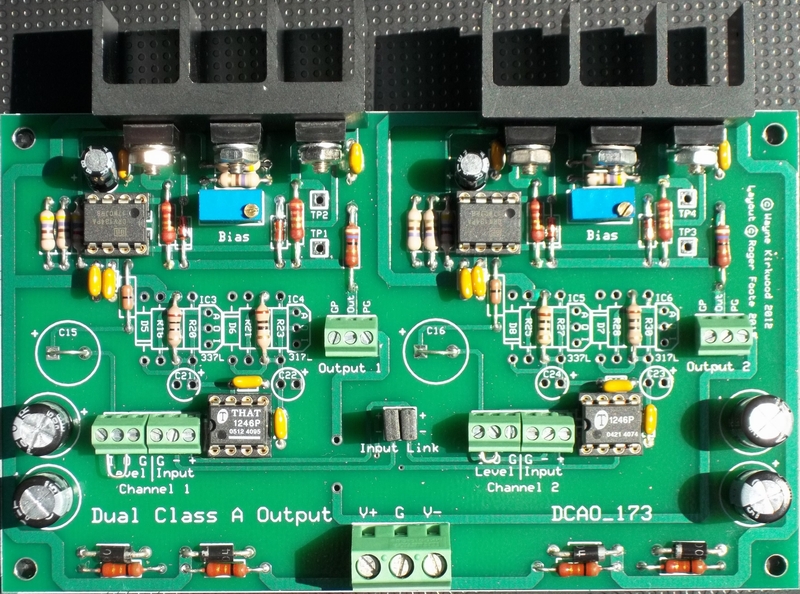 Dual Class-A Output DRV134 Reference Line Driver Build
The resistors to the left of the DRV134s hiding in the shadows are 4K7s.
The resistors under the middle power device mounting nut are 470R.
The bias pots are 1K.
The input links are set for cross-coupled (balanced) output.
The brown resistors are 1W.
The resistors in series with the DRV134 pin 7 are 0R.
Re: Dual Class-A Line and Headphone Output Board
Posted: Sun May 20, 2012 9:55 am
by mediatechnology
The old schematics I have show fully balanced operation exxcept the ones that are transformer balanced, which show low side grounded. So what you suggest should work.
Cool. What I was thinking was drive the filter network with the DCAO fully-balanced. (With the inputs cross-coupled.)
What I might add to that earlier suggestion is rather than use a single 124X to recover the filter, try a pair of 1246 cross-coupled to impedance balance the receiver. That way both legs of the filter network are terminated (to ground) by the same impedance.
If you only need an SE output to drive the DOA use only one of the 1246 outputs. That second 1246 (with its' inputs in parallel to the first) does its impedance balancing trick even if it's output isn't used.
You might pickup quite a bit of hum reduction.
Last night I tried them on some thin sounding live jazz recordings and they sounded wondrous!
What frequency range and control position do you suppose the PEQ presents to the source the most difficult load?