Page 3 of 26
Re: Phono Transfer System
Posted: Tue Oct 06, 2015 10:09 am
by JR.
While this may be academic do you have a phase response capability? If the amplitude is right the phase will probably be right.
JR
Re: Phono Transfer System
Posted: Tue Oct 06, 2015 10:47 am
by mediatechnology
JR. wrote:While this may be academic do you have a phase response capability? If the amplitude is right the phase will probably be right.
JR
I think I might, but I've never used it in either tool.
Would be fun to plot.
I did do an X-Y on the 'scope with mono generator input and RIAA EQ applied - it was razor sharp.
There was minor spread (phase shift) in the lowest octave because the film coupling caps are 5%.
I'm using 1% 10nF EQ caps so the mid range and up is spot-on.
Re: Phono Transfer System
Posted: Fri Dec 11, 2015 5:21 pm
by mediatechnology
Just got some OPA1612 SMT/DIP adapters from Brown Dog/Cimarron Technology to see how they compare in the flat preamp.
OPA1612 datasheet:
http://www.ti.com/general/docs/lit/getl ... leType=pdf
The 1612's use TI's Silicon/Germanium process in an NPN bias-compensated input.
The input voltage noise density is 1.1 nV/sqrtHz with a low 1/f corner.
The current noise is higher than the NJM2114 at 1.7 pA/sqrtHz vs. 0.4 pA/sqrtHz.
The OPA1612 - if it doesn't have the burst noise of the LME-series should be a good SMT replacement for the now discontinued LME49720.
Re: Phono Transfer System
Posted: Wed Dec 30, 2015 3:56 pm
by mediatechnology
I had Brown Dog/Cimarron make me some OPA1612 to DIP adapters to try in the Flat Moving Magnet Preamp board.
I wanted to see how the OPA1612 worked both as a moving magnet preamp as well as a moving coil application in the balanced instrumentation amp configuration here:
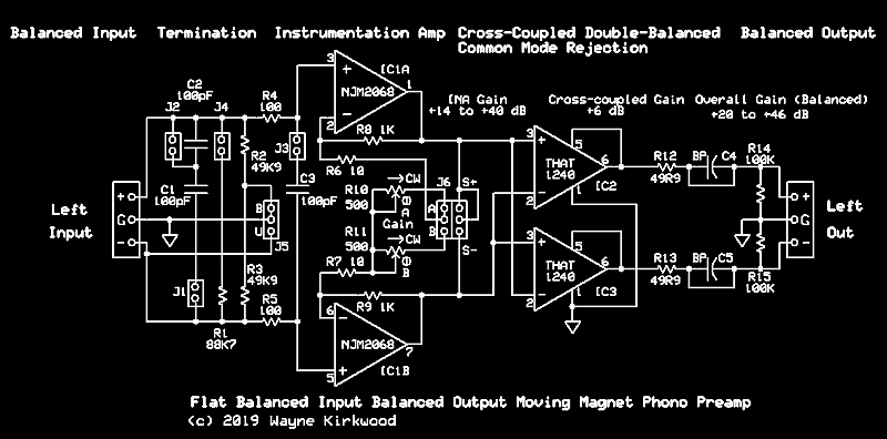 A Flat Balanced Input/Balanced Output Moving Magnet Phono Preamp
The moving magnet performance was not optimal due to the higher current noise of the OPA1612 compared to the NJM2068, NJM2114, NJM5532 and OPA2134.
The results were not a big surprise.
As a moving coil preamp the OPA1612 turns out to be pretty decent.
I modified the resistor values to lower noise making Rg 5 Ohms (total) and Rfb 499R X2.
R4 and R5 were made 0R; R2 and R3 were 499R.
The single-ended output gain is 46 dB.
Rsource was 10R. Cterm 0.
The measurement bandwidth was 20 kHz.
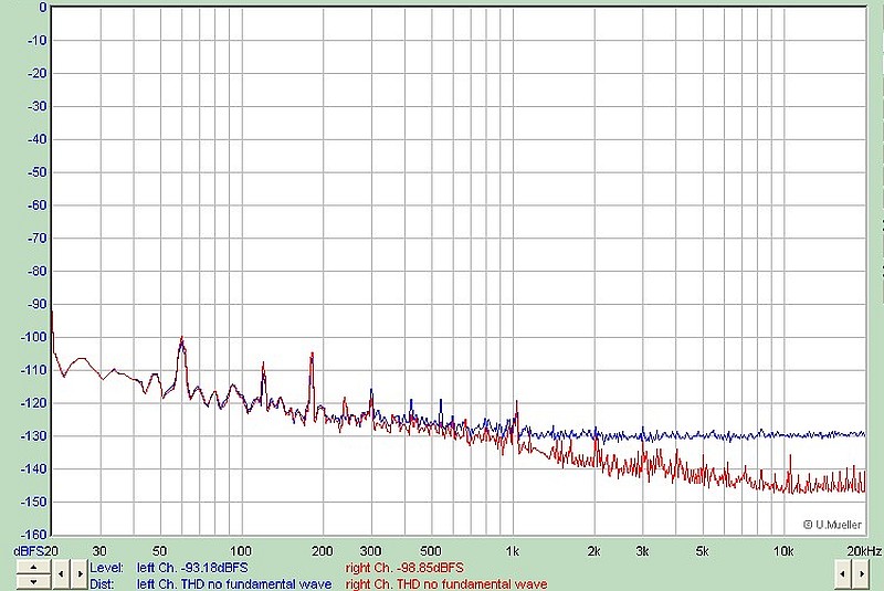 OPA1612 Moving Coil Preamp 46dB Gain 10R Source
The blue trace is the output of the preamp after the THAT1240 common mode rejection stage.
The red trace is the converter residual noise.
The ein looks to be about -131 dBu, 218 nV.
The noise density is about 1.5 nV/sqrtHz.
Though not sub-nV pretty decent for an un-assisted op amp.
The OPA1612 has respectable performance in this circuit as a moving coil preamp.
Re: Phono Transfer System
Posted: Sat Jan 02, 2016 5:27 pm
by Gold
I'm finally getting to the "demo" unit I'm going to pass around. I should be able to finish it up tomorrow. The preamp is set up for an MM cart with room to add transformers for an MC.


Re: Phono Transfer System
Posted: Sun Jan 03, 2016 3:37 pm
by Gold
Re: Phono Transfer System
Posted: Mon Jan 04, 2016 12:24 pm
by mediatechnology
Thanks for posting the pics Paul. Looks very good!
Your build reminds me that I have a couple of the Pico PSU boards I can use.
I wanted to confirm what you wrote about gain-structuring.
For +4 outputs you definitely need gain after the EQ to maintain HF headroom.
The flat preamp has a +27 dBu overload point, but the line receiver on the RIAA EQ board overloads at +21 dBu.
(It could be +27 using a THAT1246 instead of the 1240 but I thought it best not to throw away gain.)
Not much flat gain is needed. A surprisingly little amount.
For the Stanton S-681 (5 mV @ 5cm/s) through the Flat path and a final A/D overload point of +8 dBu I only need 28 dB gain total.
That' works out to be 16 dB in the instrumentation amp, +6 in the flat preamp cross-coupled output, and a final +6 dB in the EQ switcher's THAT1646.
For -10 dBu outputs I only apply about +2.25 dB gain post-EQ to makeup for the RIAA network's -2.25 dB (1 kHz) loss.
To get +4 outputs post-EQ another 10-14 dB gain is needed.
How much gain post-EQ based on 7 cm/s and your MM cart does it take to get +4?
Re: Phono Transfer System
Posted: Mon Jan 04, 2016 7:53 pm
by Gold
mediatechnology wrote:Thanks for posting the pics Paul. Looks very good!
How much gain post-EQ based on 7 cm/s and your MM cart does it take to get +4?
I have a few MM carts. I was using the AT 150MLX to test before. I don't remember how much gain I had. I've settled on adjusting the flat preamp gain to produce -6dbu @1K and adjusting post EQ gain to get to +4dBu. If my addition is right this leaves over 30db of headroom at 1k, 20dB at 10k and 10dB of headroom at 20k. There is not much on a record above 15k so this gain structure makes it very difficult to clip it.
The only thing I don't like is the gain through the EQ. When using a line input the source level would have to be dropped. I suppose I could rig a relay to drop the gain when the EQ is switched to Line. Line won't get used much so I think that's overkill.
It occurred to me that if the 1240 input for the EQ/Monitor board could drive the EQ, the first gain block after 1240 could be moved to before the Record/Phono output so the EQ could be calibrated for unity gain.
"RIAA Minimalist" Phono Transfer System Board Stuffing
Posted: Thu Jan 07, 2016 11:31 am
by mediatechnology
When I designed the signal flow for the Phono Transfer System I knew that there were going to be people who wouldn't need the entire feature set. This post shows how to stuff the PC boards for RIAA playback only applications in situations where the Flat Balanced Input Preamp and RIAA EQ board are in the same chassis. If the preamp is going to be remotely located from the EQ board, then the preamp should be built with balanced outputs (IC2 and IC22) and THAT1240s should be installed on the EQ board at IC1 and IC2.
Mouser Project Manager BOMs for the "RIAA Minimalist" configuration.
The Mouser Project Manager BOM for the Flat Preamp Unbalanced Output
Without ICs is here:
https://www.mouser.com/ProjectManager/P ... d250c298a2
The Mouser Project Manager BOM for the "Minimalist RIAA" EQ Board
Without ICs is here:
https://www.mouser.com/ProjectManager/P ... 86fa03a88a
The high-lighted areas on the stuffing diagrams below are the components needed for RIAA playback.
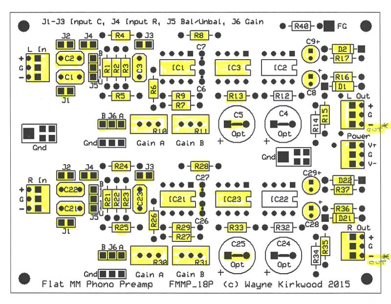 Phono Transfer System Flat Phono Preamp Board Stuffing for Unbalanced Output
Construction of the Flat Balanced Input Preamp is virtually identical with only a single THAT1240 common mode rejector IC needed per channel.
The inverting output is used to correct a signal inversion on the RIAA EQ monitor board.
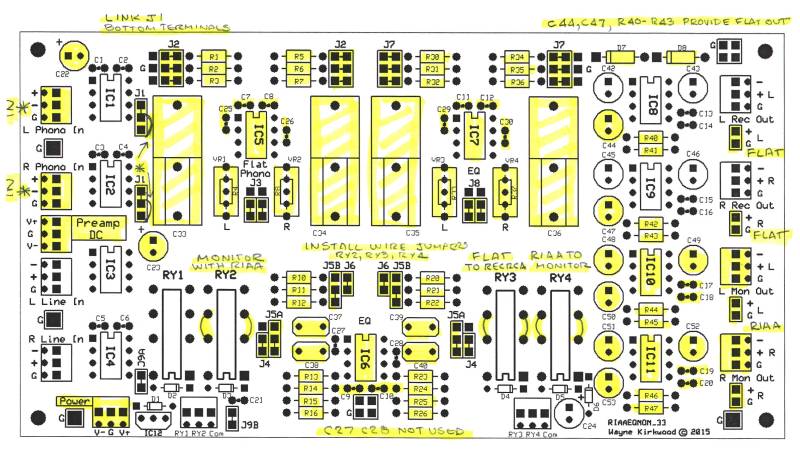 Phono Transfer System RIAA EQ Board Stuffing for Unswitched RIAA Playback
The RIAA EQ board has all of the line receiver ICs, and two line drivers removed.
The "-" input is used to receive signal from the preamp.
No relays or relay 12V regulator IC are required.
In addition to the balanced RIAA EQ output there are auxiallary RCA outputs for both the EQ'd and Flat signals.
Re: Phono Transfer System
Posted: Sat Jan 09, 2016 4:32 pm
by Gold


