If you only wanted full bypass for one device you could use one Insert Switcher board stuffed with only four relays.
You could use that to bypass either what was in the MS insert, or, in a different location the whole MS chain.
The bypass board is 24V (using 12V relays).
The coil connections float and are not tied to any ground.
Thus, if you only have +/-15 to +/-18V available you can sub-regulate the available 30 to 36V down to 24V using a 7824 or LM317 regulator.
In this configuration the regulator IC and relays common to the -15V (or -18V) rail.
The +15V rail (+18V) connects to the regulator input.
The regulator output provides +24V relative to the minus supply rail.
The relay coils "see" 24V and the relay current returns to the negative supply rail instead of 0V.
Those ebay relay boards are ideal for the solo/mute functions.
They can also be used to provide full bypass but there will be a lot of off-board wiring compared to using the insert switcher.
The device impedances seem pretty normal so I wouldn't worry about them being used in the insert.
Mid Side M-S Matrix Construction Information
-
mediatechnology

- Posts: 5466
- Joined: Sat Aug 11, 2007 2:34 pm
- Location: Oak Cliff, Texas
- Contact:
Re: Mid Side M-S Matrix Construction Information
aah amazing thanks a lot for the detailed explanation!!! i might go for the insert board instead!! maybe i get a few since it looks like a neat design and very useful, from what you just explained!!!
about power supply, i am still browsing ... i saw uber power supply from expat seems to be pretty fine! maybe you have another one you can recommend!
for power transformer, i guess toroidal 18VDC 1A is my first choice (because i think i got one lying about) but would love to stand corrected if you have a suggestion!
again, all the best!!
P
-
mediatechnology
- Posts: 5466
- Joined: Sat Aug 11, 2007 2:34 pm
- Location: Oak Cliff, Texas
- Contact:
Re: Mid Side M-S Matrix Construction Information
ive ordered velleman`s now waiting for everything! anxious! 

Re: Mid Side M-S Matrix Construction Information
I don't like crossposting, but in this case I think it's ok, otherwise, delete it
Going to build myself a new mastering console with the MS matrix (love it, use this one https://www.dagoosemusic.nl/studio/stud ... g-console/ for 7/8 years!) but in this case with the insert modules as well. It will be a 2u unit with multiple inputs and outputs, output gain, polarity swap, LR swap and It will have two inserts with MS for EQ.
I want to make it switchable froms stereo to MS, so for the passive appoach I need 8 relays (this will work, use this right now), but it's also possible to use 4 relays by having the in/out active stages stilll in line.
I was wondering if this will work without gain or other problems.
Anyone?
-
mediatechnology
- Posts: 5466
- Joined: Sat Aug 11, 2007 2:34 pm
- Location: Oak Cliff, Texas
- Contact:
Switching the Insert from MS to LR
Hi Jeffrey! It's been awhile since we've seen you here. Welcome back.
You can use a half bypass with 4 relays and I don't think the inputs would load that much.
The THAT1246 has a differential input impedance of 24KΩ.
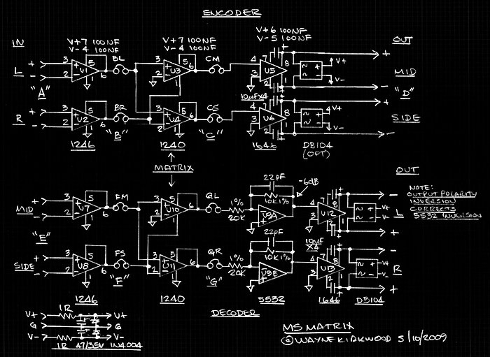
If you want to more easily switch the insert from stereo to MS and use fewer relays (2) you might consider using a DPDT relay to alternate feeding insert return CM/CS from BL/BR. That would present stereo or MS at the outputs of U5 and U6.
To handle decode use a second DPDT relay to alternate feeding return GL/GS from FM/FS. In that situation make the 20K resistors at U9's inputs 10K. Add 10K resistors in series with U10/U11's outputs. This arrangement not only switches the decode source from MS to LR but also corrects the gain change from MS decode build-up by making it -6 dB for MS and 0 dB for LR.
Sound like a plan?
You can use a half bypass with 4 relays and I don't think the inputs would load that much.
The THAT1246 has a differential input impedance of 24KΩ.
If you want to more easily switch the insert from stereo to MS and use fewer relays (2) you might consider using a DPDT relay to alternate feeding insert return CM/CS from BL/BR. That would present stereo or MS at the outputs of U5 and U6.
To handle decode use a second DPDT relay to alternate feeding return GL/GS from FM/FS. In that situation make the 20K resistors at U9's inputs 10K. Add 10K resistors in series with U10/U11's outputs. This arrangement not only switches the decode source from MS to LR but also corrects the gain change from MS decode build-up by making it -6 dB for MS and 0 dB for LR.
Sound like a plan?
Re: Mid Side M-S Matrix Construction Information
Thanks Wayne,
This was basically what I had in mind indeed, except for the 10k resistors instead of 20k. Clever!
So simply said, 20k is for MS and 10k for LR? I can do that
This was basically what I had in mind indeed, except for the 10k resistors instead of 20k. Clever!
So simply said, 20k is for MS and 10k for LR? I can do that
-
mediatechnology
- Posts: 5466
- Joined: Sat Aug 11, 2007 2:34 pm
- Location: Oak Cliff, Texas
- Contact:
Re: Mid Side M-S Matrix Construction Information
Thank you!
Yes, exactly. 20k for MS and 10k for LR.
You might want to put your name on the list for EEQ PC boards to add to the MS insert at FM/FS.
Since you already have an MS the EEQ only requires the 4 dual op amps and has bypass on-board.
http://www.ka-electronics.com/kaelectro ... tic_EQ.htm
-
mediatechnology
- Posts: 5466
- Joined: Sat Aug 11, 2007 2:34 pm
- Location: Oak Cliff, Texas
- Contact:
Original MS -6 dB Insert Modifications
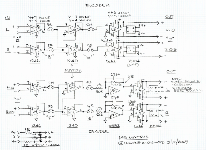
For those concerned about Mid headroom I've come up with a simple mod to lower the Insert levels by 6 dB.
1) On U3 (above) unsocket the THAT1240 IC and roll pin 2 away from the body of the IC so that it doesn't mate with the IC socket. (Pin 2 open.)
This lowers the Mid Insert Send level by -6 dB. (See: viewtopic.php?f=6&t=935)
2) Remove U4 (THAT1240) and replace it with a THAT1246. This lowers the Side gain by -6 dB.
3) Modify U9A/U9B to unity gain. Change the input resistors to 10K.
The insert levels will now be 6 dB lower and the resulting loss of gain compensated by making U9A/U9B unity gain instead of -6 dB.
Re: Mid Side M-S Matrix Construction Information
probably a good idea for a lot of uses.
Best,
Doug Williams
Electromagnetic Radiation Recorders
Doug Williams
Electromagnetic Radiation Recorders