Construction information for DIY projects, including the MS Mid Side Matrix, Elliptic Equalizer, Mastering Console, Phono Transfer System, Insert Switcher and the Dual Class-A Amplifier. You can post your baby pictures here.
I have been able to spend more than the last year patiently watching this module have its second showing. the history behind this module I know little of, but I do know that its original design was a collaboration of Wayne and his late friend. it has been a pleasure spending 2023 awaiting this module and I look forward to viewing other new builds as I have gotten the chance to see this one develop in it's entirety. thanks to everyone for putting in the time & effort - the countless emails kindly "nudging" me away from gimmicks, a forum of passionate folks to discuss such ideas. this Christmas present came late - but was surely worth the wait.
best,
Looking forward to getting this together. Like a few others, considering mating this with Roger's Pico SE in a single package....haven't pondered the gotcha's on that pipe dream yet, but I do still have one unbuilt SE PCB.
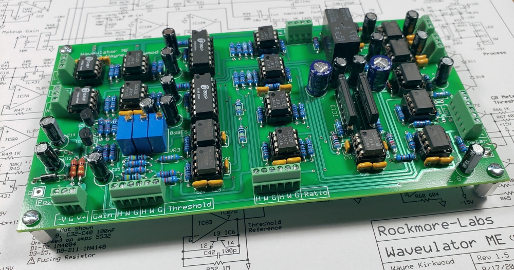
put the width & waveulator together with the parts I had at the house - was missing the dual 10k for hardness and the proper gauges for GR.
had 10-turn pots on the threshold & gain which ironically was all I had but worked out very nice
Had one led which was perfect for threshold *and worked well with the 10-turn pots*
- drums sound very nice as well as synth.
When I have my studio put back together the module correctly assembled I’ll post again - I look forward to using the hardness & will order the pot soon - but glad to see everything powered up, passed signal & had no noise issues
*I left the ground from the IEC floating*
Thanks for the module/s - looking forward to this fall
***The width module alone blows my mind every time I hear it — that module alone is timeless***
After spending about a week on IT support for the store I'm finally returning back to documenting Waveulator test.
They say a picture is worth a thousand words so I'm posting some of the waveforms that will be in the test section of the pdf.
Note that the input and output 'scope measurements are single-ended whereas the balanced differential level specified is 6 dB higher.
In otherwords the measured voltage level of the input and output waveforms on the scope are half what they actually are at the balanced inputs and outputs.
Waveulator Detector Output measured at Ratio Terminal "H". 0dbu Input. Threshold Terminal "W" set at 0V.
Waveulator Detector Output versus Input. Measured at Ratio Terminal "H". 0dbu Input. Threshold Terminal "W" set at 0V .
Waveulator Detector Output versus Input. Measured at Ratio Terminal "H". +6dbu Input. Threshold Terminal "W" set at -0.75V.
Waveulator Output vs Input with 0dbu In. Threshold "W" set 0V. Ratio Max.
Waveulator Output vs Input with +8dbu In. Threshold "W" set at 0V. Ratio Max.
Longtime listener, first time caller - I'm almost done building a standalone Waveulator for a friend and got it up, running, and calibrated last week.
Around the time that I finished calibrating, one of the artists that I work with sent new tracks for an ep that we'd been going back and forth on, to be mastered. With the Waveulator last in the chain, and a hair of gain reduction, the mixes sounded really thick and brought out detail that I was originally struggling to bring out. The artist approved when the new masters were sent back.
I'm using 23 step switches for threshold and makeup gain. I had 10K linear pots in both positions originally, to see how the taper of the pot affected the behavior or the device. I noticed that, for threshold, gain reduction started kicking in around 11:00 with a linear taper pot.
I wanted this to happen earlier, with the stepped switch it does this by adding appx 850 ohms of resistance in the first/last positions, and alternating 430/460 (have to check the exact value again) ohm resistors for the other steps. This felt a little bit unconventional but worked!
Makeup gain mimics a 10K linear taper, so same value repeating each step.
I still have a pot in for ratio. I'm using a dual100K linear taper pot, with 10K resistors across lugs 1 & 3 to mimic a 10K anti-log taper. This seemed to increase the resolution for the ratio. I'm still trying to come up with resistor values for the switches. If anyone knows of a calculator or equation I can use to figure that out, that would be great.
Anyways, I've included pictures . I used a laser engraver (XTool D1, 10 watt) for the panel. The mA meter (120 ohm) I bought on Amazon, scanned the dial and printed a sticker for the gain reduction values. Wayne helped with the resistor values for the meter locations (huge thanks again!!) and the meter is spot on after those positions were updated. I had some 1k, 10% carbon resistors left over from restoring an old Hallicrafters radio, and found one that matched the exact value (1k4) that I needed for the 10 dB meter range.
Stoked to build mine next, thanks for the great project!
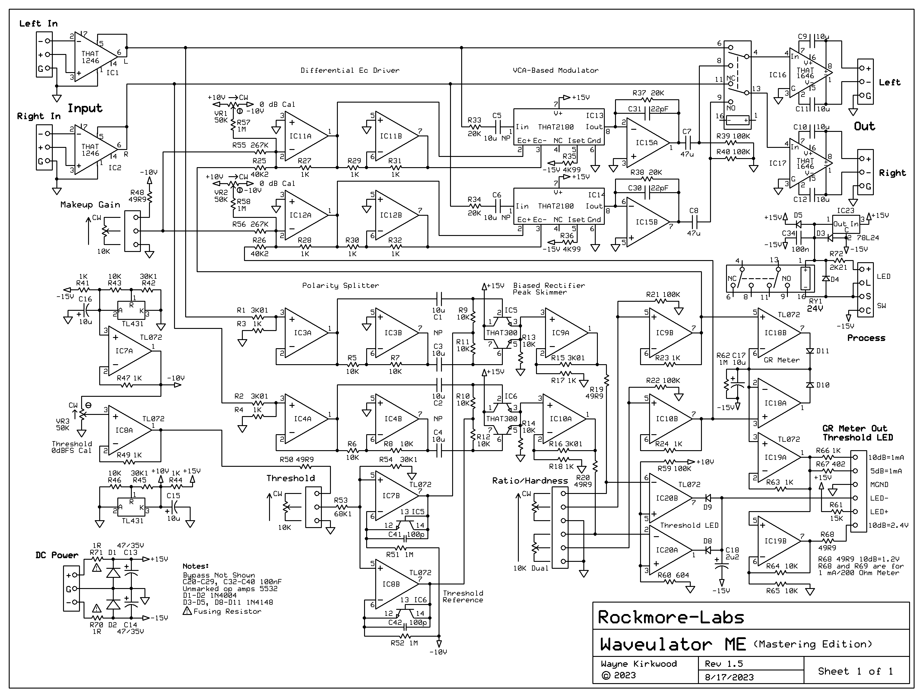
For the Threshold you can set the range by adjusting VR3.
If you want the max CW rotation of the control to correspond to the converter's 0 dBFS, run tone at the input at that level and adjust VR3 until the Threshold LED just begins to turn on.
With VR3 at max the "0" point of Threshold is +27 dBu which is probably 3 to 9 dB hotter than the converter's overload point.
Lowering VR3 will give you some more range at the low end.
You still may need that bowing resistor however.