OK, it has taken quite a while, but my AES colleague Ian DuRieu has talked Graeme Cohen into presenting his perspective of the preamp that is the subject of this thread. It can be found here http://leonaudio.biz/cohen.htm Thanks Ian and Graeme, enjoy!
Keith Taylor
Benchmark Mic Preamp from 1984 - Active Preamp History
-
Keith Taylor
- Posts: 2
- Joined: Tue Jul 08, 2008 7:58 am
-
mediatechnology

- Posts: 5466
- Joined: Sat Aug 11, 2007 2:34 pm
- Location: Oak Cliff, Texas
- Contact:
Re: Benchmark Mic Preamp from 1984 - History
Thanks Keith that pdf provides a lot of explanation of all the factors that make Cohen's work unique.
I think one of the sources of confusion was that virtually any preamp using the "op amp 'round the transistors" bias scheme was being coined as being the "Cohen" topology in other fora - even examples which were not fully-balanced. That was certainly the source of my confusion reading those threads and that point I was trying to make was we had seen the bias scheme before. I've never seen a fully-balanced topology in the literature that predates Cohen's and I've seen quite a few since crediting him. Now, we have Cohen himself to set the record straight and I appreciate him doing that.
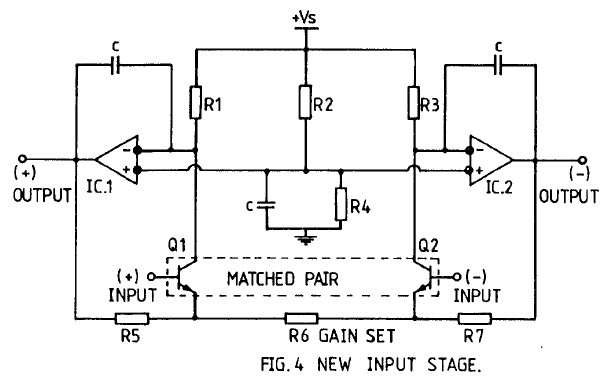
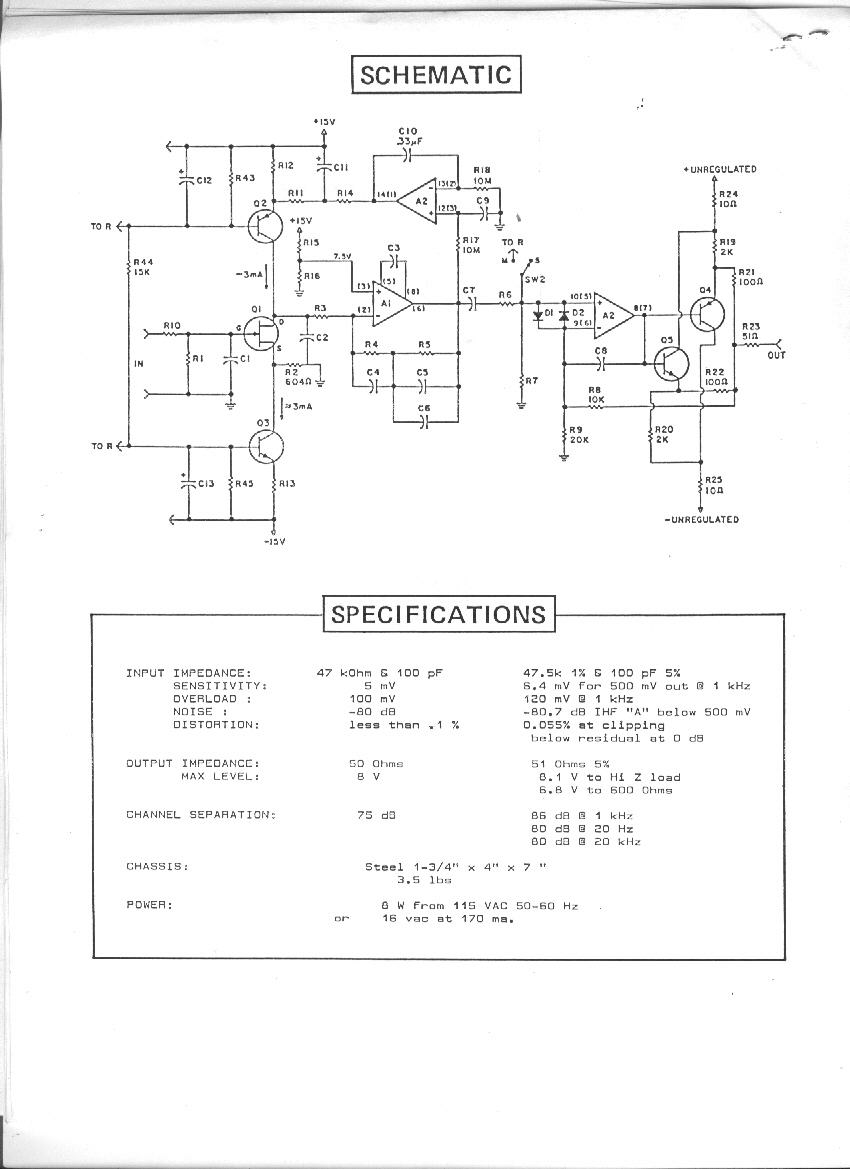
What had me confused was in Cohen's original paper this section:
I've shortened this for reading, the web site link has the full AES document.
That description is accompanied by this figure:
My first thought was "I think I've seen that somewhere." I looked at the Burdick schematic I had and wondered "did these guys talk?" That's what started me digging and I also found the Harrison (1978) , JR and bcarso the Mothchenbacher-Fitchen (1973) with Samuel Groner finding the Demrow citation. (1968)
Mr. Cohen has now clarified below what he meant by "new" when he wrote the 1984 AES paper:
OK, that explains the confusion. There are indeed many unique attributes that when summed in the entire preamp make it unique. But looking at figure 4 it's easy to draw the conclusion that figure 4, in isolation, was thought to be new.
The post here, which was copied from the original discussion at Prodigy-Pro, doesn't contain explanation of the differences in the various examples we cited. The early citations are instrument amps not preamps. But, each are examples of the biasing scheme some of which, the instrumentation amps in particular, wouldn't make very good preamps. The biasing was the object of comparison at Prodigy though admittedly that's not made clear here in this hastily-copied thread.
The Harrison preamp wasn't a particularly good one either and I hated servicing them. The current sources did make them noisier. Fortunately, because of that however I have more than a few LM394s. On the Benckmark the main thing that had Al going was the 2SB737 and yes it's not DC-coupled nor fully-balanced. I don't recall, but I'm fairly certain he had seen the Harrison. But, they are all similarly biased.
The point is that the biasing scheme was pretty well known (though not necessarily to Cohen) prior to 1984 without a clear point of origin. The trail seems to stop at Demrow in 1968 but who knows where he may have seen it.
I'm glad Mr. Cohen has told us what he thinks was "new" about it after so many years and thank him for sharing the great material and provding clarification and insight. I think most of the confusion was ours. I've done more than few things myself thinking they were "new" when there was prior work. I found a sum/difference network I used in the M/S decoder recently in a 1995 Burr-Brown catalog.
He's lucky to have been able to do a hybrid. Reading some of Derek Bower's papers on the SSM preamps he points out that SSM didn't have thin film resistors - only diffused - and that drove the topology of the SSM2015 and 2016. Once production of SSM moved to Analog Devices he had a laser-trimmed process available and it allowed him to make the SSM2017 with on-chip resistors.
Thanks again Keith for getting Mr. Cohen to contribute here.
I think one of the sources of confusion was that virtually any preamp using the "op amp 'round the transistors" bias scheme was being coined as being the "Cohen" topology in other fora - even examples which were not fully-balanced. That was certainly the source of my confusion reading those threads and that point I was trying to make was we had seen the bias scheme before. I've never seen a fully-balanced topology in the literature that predates Cohen's and I've seen quite a few since crediting him. Now, we have Cohen himself to set the record straight and I appreciate him doing that.
What had me confused was in Cohen's original paper this section:
I've shortened this for reading, the web site link has the full AES document.
That description is accompanied by this figure:
My first thought was "I think I've seen that somewhere." I looked at the Burdick schematic I had and wondered "did these guys talk?" That's what started me digging and I also found the Harrison (1978) , JR and bcarso the Mothchenbacher-Fitchen (1973) with Samuel Groner finding the Demrow citation. (1968)
Mr. Cohen has now clarified below what he meant by "new" when he wrote the 1984 AES paper:
OK, that explains the confusion. There are indeed many unique attributes that when summed in the entire preamp make it unique. But looking at figure 4 it's easy to draw the conclusion that figure 4, in isolation, was thought to be new.
The post here, which was copied from the original discussion at Prodigy-Pro, doesn't contain explanation of the differences in the various examples we cited. The early citations are instrument amps not preamps. But, each are examples of the biasing scheme some of which, the instrumentation amps in particular, wouldn't make very good preamps. The biasing was the object of comparison at Prodigy though admittedly that's not made clear here in this hastily-copied thread.
The Harrison preamp wasn't a particularly good one either and I hated servicing them. The current sources did make them noisier. Fortunately, because of that however I have more than a few LM394s. On the Benckmark the main thing that had Al going was the 2SB737 and yes it's not DC-coupled nor fully-balanced. I don't recall, but I'm fairly certain he had seen the Harrison. But, they are all similarly biased.
The point is that the biasing scheme was pretty well known (though not necessarily to Cohen) prior to 1984 without a clear point of origin. The trail seems to stop at Demrow in 1968 but who knows where he may have seen it.
I'm glad Mr. Cohen has told us what he thinks was "new" about it after so many years and thank him for sharing the great material and provding clarification and insight. I think most of the confusion was ours. I've done more than few things myself thinking they were "new" when there was prior work. I found a sum/difference network I used in the M/S decoder recently in a 1995 Burr-Brown catalog.
He's lucky to have been able to do a hybrid. Reading some of Derek Bower's papers on the SSM preamps he points out that SSM didn't have thin film resistors - only diffused - and that drove the topology of the SSM2015 and 2016. Once production of SSM moved to Analog Devices he had a laser-trimmed process available and it allowed him to make the SSM2017 with on-chip resistors.
Thanks again Keith for getting Mr. Cohen to contribute here.
-
mediatechnology
- Posts: 5466
- Joined: Sat Aug 11, 2007 2:34 pm
- Location: Oak Cliff, Texas
- Contact:
Cohen Photos
I wanted to share the photos with you available on the link above courtesy of Graeme, Ian and Keith. For more information visit Ian's site http://www.leonaudio.biz/ and obtain the pdf http://leonaudio.biz/cohen.htmOK, it has taken quite a while, but my AES colleague Ian DuRieu has talked Graeme Cohen into presenting his perspective of the preamp that is the subject of this thread. It can be found here http://leonaudio.biz/cohen.htm Thanks Ian and Graeme, enjoy!
Keith Taylor
There you'll find Graeme's comments about his preamp and some of the differences between it and the instrumentation amps discussed in this thread. Ian was kind enough to let me post the images here. Thanks guys.
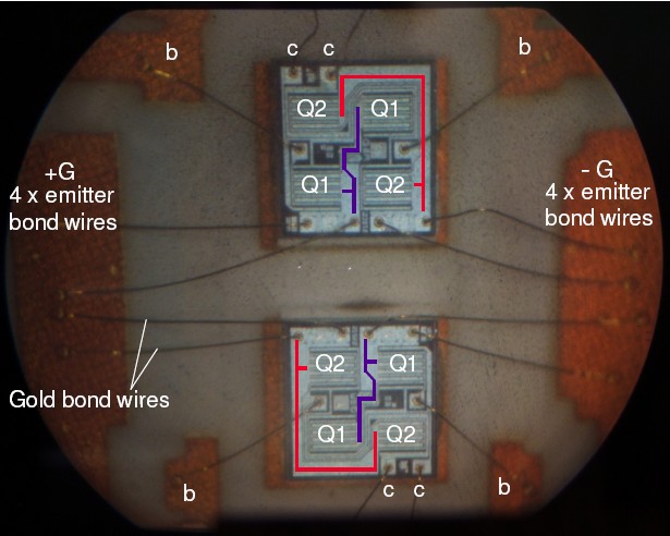
The LM194 input transistors on the OM1556. Image courtesy of Graeme Cohen and Ian DuRieu.
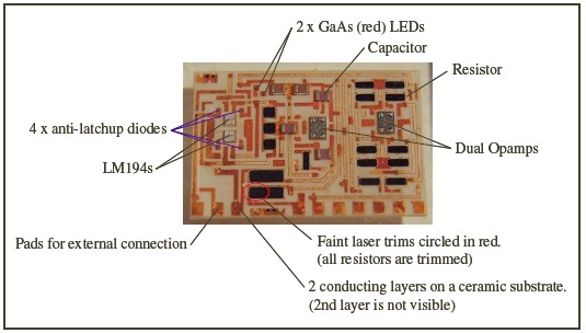
An overview of the OM1556. Image courtesy of Graeme Cohen and Ian DuRieu.
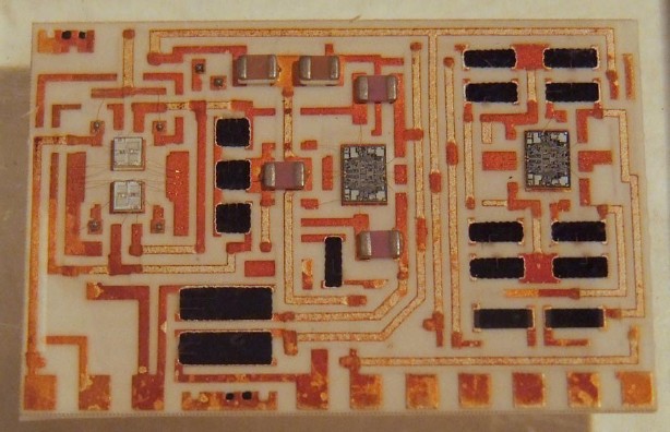
A closeup of the OM1556. Image courtesy of Graeme Cohen and Ian DuRieu.
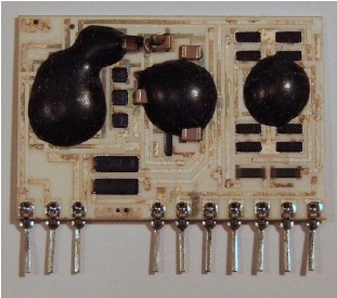
OM1556 Preconformal coating. Image courtesy of Graeme Cohen and Ian DuRiue.
OM1556 Conformal coating. Image courtesy of Graeme Cohen and Ian DuRiue.
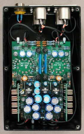
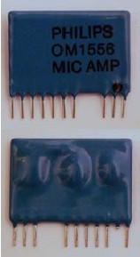
An OM1556 Preamp. Image courtesy of Graeme Cohen and Ian DuRieu.
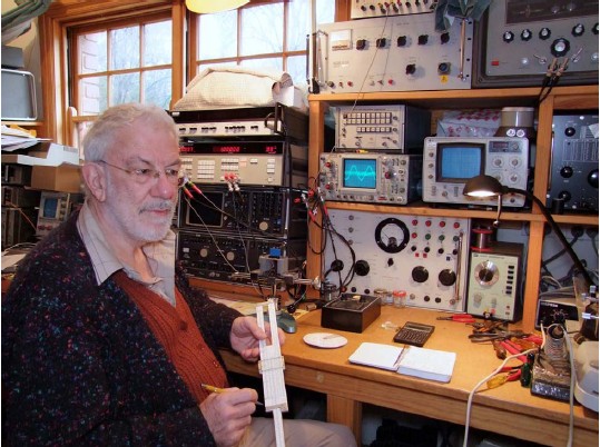
A "serious" Graeme Cohen in his workshop July 2008. Image courtesy of Graeme Cohen and Ian DuRieu.

Re: Benchmark Mic Preamp from 1984 - Active Preamp History
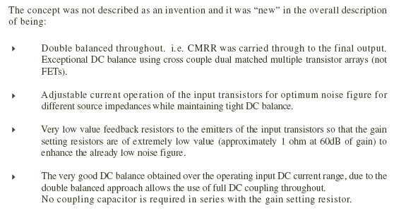
I appreciate his clarification that he doesn't consider it invention, and the distinction that his design passes CM signals through to the outputs. Passing the common mode through to the output doesn't really strike me as a benefit. When dealing with raw signals I prefer to squash out of band and undesirable signals (noise) at the earliest possibility. I've considered passing the common mode out to balanced outputs in simple stand alone preamps to save some circuitry but I worry about the CM range of following line inputs. If somebody plugs your preamp into their line input and it sounds bad because they can't handle the CM, they are not going to be receptive to any explanation that you are not at fault. I am not suggesting that most applications will routinely have dangerous CM signals. I guess that depends on how the preamp input is terminated. The old TRANSAMP IIRC used something like 100k to ground on each input with the nominal 2k mic termination floating between pins 2 and 3, so the CM input impedance is pretty high relative to signal input impedance.
Every console/mixer I ever designed with preamps built in, single ends the mic preamp output and then routes it around internally as a single unbalanced line referenced to local grounds with differential amps as needed. So again to use his preamp design requires an additional differential amp inside to maintain the CM output, then another differential following to remove the CM. A benefit perhaps if you sell opamps
JR
Cancel the "cancel culture", do not support mob hatred.
-
mediatechnology
- Posts: 5466
- Joined: Sat Aug 11, 2007 2:34 pm
- Location: Oak Cliff, Texas
- Contact:
Re: Benchmark Mic Preamp from 1984 - Active Preamp History
Thanks JR.
It occurred to me that if the next thing the fully-balanced preamp saw was a transformer it would have near infinite CMR at audio frequencies.
What I've found interesting about following the history of the integration of microphone preamps is that integrated resistors were the hardest part. Laser trimming helped a lot but there's still a lot of magic in resistors. Fortunately Bowers just came out and said this in his SSM2016 paper. The early SSM2017 datasheets label the part a "Self Contained" preamp. The fact it had on-chip resistors was a big deal.
Too bad we don't have a hybrid lab where we can build stuff like Cohen's. Those photographs were taken through some 25 year old Lucite and I thought they were so cool. Ian did a great job in documenting this.
Re: Benchmark Mic Preamp from 1984 - Active Preamp History
I'm not up on my semiconductor physics but I recall back in the '70s when working with monochips (semi custom ICs), you could get real resistors below a couple hundred ohms, but large resistances were made from pinch (?) resistors, and they were not very quiet or linear.
I recall an early national IC, maybe late '80s (don't recall PN) with good resistors in a switched matrix. I think it was designed for a graphic EQ or something, but the resistors could also be used for gain scaling or whatever. Around that time you could also buy resistor arrays in IC packages (Thin film?), but those seem to have faded, at least from my view point.
JR
Cancel the "cancel culture", do not support mob hatred.
-
mediatechnology
- Posts: 5466
- Joined: Sat Aug 11, 2007 2:34 pm
- Location: Oak Cliff, Texas
- Contact:
Re: Benchmark Mic Preamp from 1984 - Active Preamp History
Bowers apparently only had diffused resistors at SSM. He wrote this in regard to the SSM2016 in the 1987 AES Preprint 2495.

By the time PMI acquired the company they had laser-trimmed capability in the SSM2141 line receiver but it wasn't until the ADI purchase of PMI that he was able to do the SSM2017. I think the technology was there, just not in SSM's early fab facilities.
I should post the SSM2015 and 2016 diagrams. When you look at the 2017 in comparison you wonder "Why did he do it that way when he could have done it like the 2017 or AD524?" Fortunately he tells us. When you see all the trimmed Rs - 4 for the output stage alone - it becomes obvious just how much precision is needed.
I suppose that's part of the beauty of Cohen - the next stage downstream has to deal with the CMR.
If you compare 5534 schematics you will see the bias source drawn as a FET, a resistor, or a pinch. I think they have horrible tolerance and tempco.but large resistances were made from pinch (?) resistors, and they were not very quiet or linear.
-
Ian DuRieu
- Posts: 5
- Joined: Fri Aug 01, 2008 9:07 pm
- Location: Adelaide, South Australia
- Contact:
Re: Benchmark Mic Preamp from 1984 - Active Preamp History
Hi JR,
Please see Figure 1 on page 2 of the PDF file for the full circuit which includes a pair of 4 resistor diff amps on the output.
The PDF file is at http://leonaudio.biz/cohen.htm
Cheers
Ian DuRieu
It sounds like you may have only seen figure 4 as posted by others. This is only the input stage.JR. wrote:Passing the common mode through to the output doesn't really strike me as a benefit.
Please see Figure 1 on page 2 of the PDF file for the full circuit which includes a pair of 4 resistor diff amps on the output.
The PDF file is at http://leonaudio.biz/cohen.htm
Cheers
Ian DuRieu
Re: Benchmark Mic Preamp from 1984 - Active Preamp History
Thanks, I wish I could use that excuse, but I just skimmed through the pdf linked to and missed that "E" is apparently grounded. I guess "E" stands for earth (?). 
I'd have to spend more time looking at an actual implementation to find the claimed advantage of that topology vs, the more common single differential amp. Perhaps for a stand alone preamp, the + and - audio paths are more symmetrical and better matched, but in every case where I used this general topology the preamp output was routed to other circuitry for additional processing, so carrying the audio path internally as two differential lines was impractical.
Perhaps ironic in light of my protestations I have kicked around a "differential-in to differential-out" circuit block for use in a mic preamp whose input circuitry is allowed to float up to phantom voltage.

Sorry I don't mean to hijack your thread , and for any playing along at home, this circuit has not been tested so may not even work. Using a three transistor long tail pair for the differential amp appears similar in function to your two opamp diff to diff. But this is just mental doodling, I don't see much market for a stand alone mic preamp.
Back to the original topic, the only thing similar (I have published) was a phono preamp kit I sold back in the '80s. This schematic only shows the moving magnet version so you need to mentally substitute low noise bipolars (used in moving coil version) where JFETs are, and bias the input stage opamp pair up to V+/2. The MC input devices were low noise PNPs and their bias current was supplied via the feedback resistors similar to your referenced design.
I also appreciate that the subject topology has response to DC and I have a pole in my open loop path, that ultimately reflects in a LF roll off to closed loop path, but this pole is set quite low.
Welcome to PICO and Prodigy, and where ever else you have posted this info. It is good to learn more about the history of this. I hope I don't sound dismissive or contrary.
JR
I'd have to spend more time looking at an actual implementation to find the claimed advantage of that topology vs, the more common single differential amp. Perhaps for a stand alone preamp, the + and - audio paths are more symmetrical and better matched, but in every case where I used this general topology the preamp output was routed to other circuitry for additional processing, so carrying the audio path internally as two differential lines was impractical.
Perhaps ironic in light of my protestations I have kicked around a "differential-in to differential-out" circuit block for use in a mic preamp whose input circuitry is allowed to float up to phantom voltage.
Sorry I don't mean to hijack your thread , and for any playing along at home, this circuit has not been tested so may not even work. Using a three transistor long tail pair for the differential amp appears similar in function to your two opamp diff to diff. But this is just mental doodling, I don't see much market for a stand alone mic preamp.
Back to the original topic, the only thing similar (I have published) was a phono preamp kit I sold back in the '80s. This schematic only shows the moving magnet version so you need to mentally substitute low noise bipolars (used in moving coil version) where JFETs are, and bias the input stage opamp pair up to V+/2. The MC input devices were low noise PNPs and their bias current was supplied via the feedback resistors similar to your referenced design.
I also appreciate that the subject topology has response to DC and I have a pole in my open loop path, that ultimately reflects in a LF roll off to closed loop path, but this pole is set quite low.
Welcome to PICO and Prodigy, and where ever else you have posted this info. It is good to learn more about the history of this. I hope I don't sound dismissive or contrary.
JR
Cancel the "cancel culture", do not support mob hatred.
-
mediatechnology
- Posts: 5466
- Joined: Sat Aug 11, 2007 2:34 pm
- Location: Oak Cliff, Texas
- Contact:
Re: Benchmark Mic Preamp from 1984 - Active Preamp History
Here's the Cohen circuit Ian is referring to:
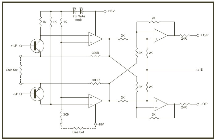
Image courtesy of Graeme Cohen and Ian DuRieu.
The two LEDs are frequently discussed. Graeme mentions them in his FAQ here:
http://leonaudio.biz/double.balanced.mi ... df#page=10
I just noticed that the upper and lower output diff amps could be made out of a pair of THAT1240s. The Rfb would be 9K vs. 2K but the CMR very high due to the close internal resistor match of ~0.005%.