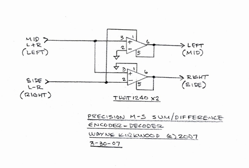
This precision sum difference matrix for M-S mid side uses the 0.005% matched internal resistors of the THAT1240. It encodes or decodes depending on how you define the inputs and outputs.
Guys - Roger has kicked around the idea of doing an M-S board based on this trick using the 1240. What I'm thinking we would want to do is a board which provides simultaneous encode/decode with relay bypass. Would we also want it to be balanced I/O?
I thought the universal encoder wouldn't have an output. That makes it truly universal.
OK, so far we have simul encode/decode, balanced I/O, relay bypass, and InGenius (optional) balanced inputs for the I/O. (Still need to use 1240s for the internal stages.)
Note to "self" - make sure the balanced I/O driver has the option to preload the output in 600 ohms. This is required when SSM2142s are used instead of THAT1646s. The SSM 2142 does not have precise unity gain unless terminated.
I was thinkin about this circuit today, It would be perfect to put in my soon to be upgraded Mastering Console, i could use a few inserts with a M/S option, the relay idea sounds good!
Thanks everyone for your input and support. I'm still figuring out what the best bypass option is.
It could be bypassed ahead of the balanced driver and receiver, taking only 2 relay poles, or it could provide bypass through the balanced I/O. In that case it could be full or half bypass taking 4 or 8 poles.
That makes the most sense. The only downside I see to it, as opposed to completely bypassing the ahead/behind of the line driver/line receiver, is that loading of the encoder output, by the external device, reduces separation in bypass. The 25R build-out of the 1646 is very low, but 600 ohm loads would lower it enough to degrade bypassed separation.
The half bypass system used in the Pico Compressor works fine. In that situation we don't have to maintain 0.02 dB gain accuracy. In the matrix I'm not concerned by the load of the line receiver but the load on the line driver on the insert send by the external processor. This only applies if the bypass is internal to the encoder/decoder in the M-S domain. One could bypass completely around the entire encoder/decoder in the L/R domain as is done in the Pico Comp. That may be the simplest way though it might not A/B as well.
If A/B monitoring through the encoder/decoder and encoder/process/decoder in the M-S domain is the goal, (and it may not be) then bypass of the insert is required. In bypass, the M-S encoder has a very tight gain matching requirement to maintain encode/decode separation when monitoring through it end-to-end (E-E).
The following discussion is based on the M-S matrix being bypassed between the encode/decode insert in the M-S domain. That way, in bypass, monitoring through the encode-decode system is done without added mid, side (or both) processing or level shifts. (Full E-E monitoring.)
Outside the matrix gain error doesn't matter as much because it affects only channel balance. Inside the matrix it takes very little dB error to make the difference, in bypass, between 40 and 80 dB separation. The numbers go from 0.5% to 0.005%.
If the output of the encoder is loaded by whatever's loading the insert send, and half bypass switches to bridging the external processor's input, e.g. the insert send, there will always be a variable gain error caused by the external processor's load on the 1646's encoder. That's fine if both the encoder's mid and side outputs are loaded by the same amount. But they might not be. Only one channel, mid or side, may have a load and processing at all. Even if mid and side have the same termination impedance, it's doubtful that with 5% or 1% termination resistors the gain error caused by their inputs is within 0.005%. So when bypass is switched in, the gain error, just due to external loading, is enough to reduce unprocessed separation to less than that of the source. My concern is not the load introduced by the decoder's line receiver, but by the load on the encoder by the external processor's termination resistance. Even in bypass, patching or unpatching something to the send could change the separation considerably.
Look at it this way: The gain accuracy of the 1240 is +/- 0.05 dB maximum. We depend on that for ultra-high separation in E-E monitoring. The 1646, driving the external loop send output, has a gain accuracy of +/- 0.2 dB when loaded in 100K. Loading a 1646 in 600 ohms drops the output level another 0.7 dB. Thus, the total gain error in the 1646 can be as high as 1.2 dB depending on it's own error and load impedance.
To maintain accuracy in E-E monitoring, bypass has to be ahead of the balanced line driver and therfore after the decoder's line receiver. Full bypass gets you closer than half-bypass, but not as close as bypassing the line driver's gain error completely. E-E monitoring may not be a requirement but it would seem to provide more accurate A/B comparisons.
When not bypassed, I'm not sure gain accuracy matters as much as the point is to alter the sound (and separation) anyway. When processing is engaged separation is going to be modified tremendously.
But with half bypass, my concern is that listening to the matrix in E-E is going to be separation reduced and that A/B comparisons of processed/unprocessed are not going to be as valid.
My thinking is that the most gain accurate bypass will involve taking the signal ahead of the encoder's 1646 (single-ended) and feeding that to the N.O. contact. The second contact, N.C., would be after the decoder's line receiver. The primary advantage to this is that it eliminates two stages' gain error plus loading error. An added advantage is that it takes only a SPDT relay per channel.