Thanks for sharing that JR. Bob had contacted me about a month ago about this project and I was thinking about pinging him to see how it was going.
I'm really anxious to see how it sounds.
More on the NuTube: viewtopic.php?f=12&t=870
Mid Side M-S Matrix Uses No Precision Resistors
-
mediatechnology

- Posts: 5458
- Joined: Sat Aug 11, 2007 2:34 pm
- Location: Oak Cliff, Texas
- Contact:
Re: Mid Side M-S Matrix Uses No Precision Resistors
It looks like the last post about varying the M and S level is on page 20. This is a ganged variable width version. For my application I want separate controls for varying the level of both the M and the S channel. I want +/- 3dB on each channel. I'll change the gain of U9 to 3dB.
Should I use the portion of a 10k resistor string that gives me the range I want on the rotary switch and use an off board resistor to make up the rest of the 10k value? In other words have it look like the variable width circuit with the variable part at the top of the throw and a fixed resistor to make up the rest of the resistance. Is there a better way to do it? I
Should I use the portion of a 10k resistor string that gives me the range I want on the rotary switch and use an off board resistor to make up the rest of the 10k value? In other words have it look like the variable width circuit with the variable part at the top of the throw and a fixed resistor to make up the rest of the resistance. Is there a better way to do it? I
-
mediatechnology
- Posts: 5458
- Joined: Sat Aug 11, 2007 2:34 pm
- Location: Oak Cliff, Texas
- Contact:
Re: Mid Side M-S Matrix Uses No Precision Resistors
Paul that would be my choice given that the "pot" you'll be using is actually a stepped resistor and has good end-to-end tolerance.Should I use the portion of a 10k resistor string that gives me the range I want on the rotary switch and use an off board resistor to make up the rest of the 10k value?
Re: Mid Side M-S Matrix Uses No Precision Resistors
Thanks Wayne. One more question. Would you scale R in and R f differently for 3dB gain? The maximum output impedance from the pot would be about 2.5k i believe. Is 20K the minimum input impedance you would use? If R in is 20k Rf should be 28.3k which is not a standard value. If I want exactly 3dB maximum gain should I set the op amp up for more than 3dB gain and use an off board resistor to trim the gain at the pot? Should i scale the values until I hit on a standard value combination? What would you do?
-
mediatechnology
- Posts: 5458
- Joined: Sat Aug 11, 2007 2:34 pm
- Location: Oak Cliff, Texas
- Contact:
Re: Mid Side M-S Matrix Uses No Precision Resistors
The 20K loading the 2.5KΩ Thevenin equivalent of the pot is going to introduce about a 1 dB gain loss error. But if you have it installed in both Mid and Side the ratios remain the same so you may not need the following options.
The gain error from using 28K/20K vs 28K25/20K (3 dB) is going to be about 0.075 dB so it may not matter.
Two other options:
A) Buffer the wiper with a unity gain voltage follower. (If you use a bipolar op amp with input protection diodes be sure to put a 1KΩ or so in the feedback loop to limit fault current and prevent latch-up.) A follower requires a bias resistor for the non-inverting input or make-before-break switch to maintain a DC path during switching. (Most 24 Pos Elmas are MBB.)
B) Use a fixed input resistor and vary Rfb around the 5532 like the gain R in the MTC-IGFO: viewtopic.php?f=6&t=921
I like B better since you don't have to worry about bias resistor or input resistor loading to obtain accuracy.
For option B you don't have to have a MBB switch (but its best) if you wire it so the wiper ties to one end. (See: http://www.ka-electronics.com/images/pn ... heet_3.png)
If you go with option B make the stepped resistor normalized to 10KΩ and then set the input R and a stop resistor to set the range to ±3 dB.
I used a shortcut to calculate that using a 10K input, calculating Rstop and Rgain and then normalizing Rgain to 10K and scaling Rin and Rstop working backwards. Maybe its because I'm math impaired somedays but I hit the +/- 5.5dB values with 1% Rs to 0.01 dB.
FWIW there's a handy R96 page here: http://logwell.com/tech/components/resistor_values.html
Re: Mid Side M-S Matrix Uses No Precision Resistors
I didn't consider option B because there will have to be at least a 6 inch wire run from the PCB to the switch. I thought that was too long for option B. No?
-
mediatechnology
- Posts: 5458
- Joined: Sat Aug 11, 2007 2:34 pm
- Location: Oak Cliff, Texas
- Contact:
Re: Mid Side M-S Matrix Uses No Precision Resistors
Look at how the shield is handled in the MTC-IGFO or Flat Moving Magnet Preamp in the PTS.
The shield is driven by output, to provide a low AC impedance to ground, and the inner conductor the return to the stop resistor. The cable capacitance appears in parallel with the feedback resistor harmlessly and the shield effectiveness is the same as if it were grounded.
The shield is driven by output, to provide a low AC impedance to ground, and the inner conductor the return to the stop resistor. The cable capacitance appears in parallel with the feedback resistor harmlessly and the shield effectiveness is the same as if it were grounded.
Re: Mid Side M-S Matrix Uses No Precision Resistors
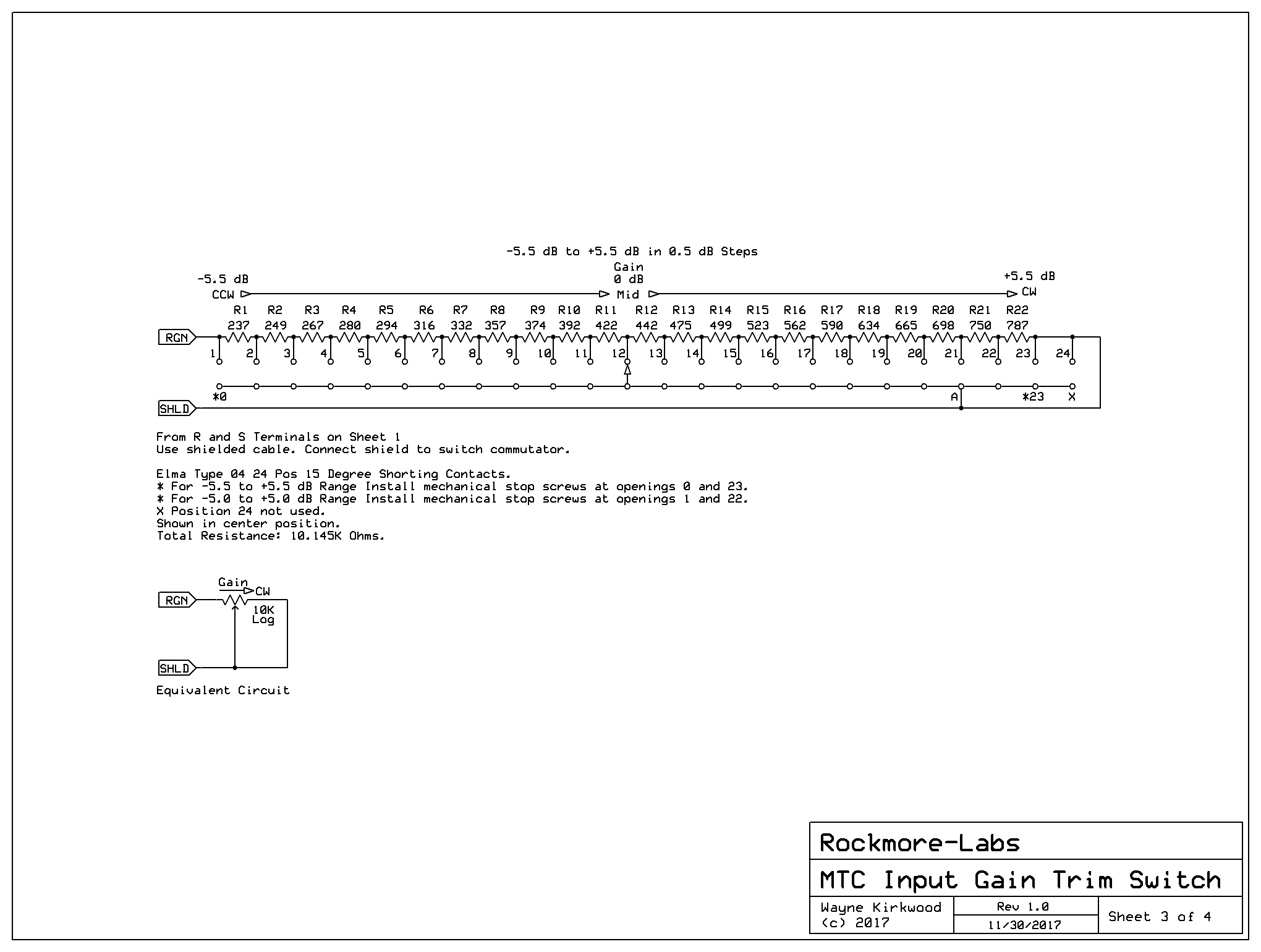
Ahh, I didn't think of the driven shield. Looking at the MTC as an example I think I can ignore R2 and R3. Those are for the +5dB gain offset, right? So IC3A is configured for unity gain with R1 (7K5) and R4 (7K5) if you ignore the feed to the pot. What is the purpose of R5 and how is the value determined?
Would I set U9 on the M/S board for unity gain with 20k resistors and use a 10K resistor to feed the trimmer and adjustment pot? I guessed 10k because R5 (3K74) in the MTC is half the value of R4 (7K5).
Would I set U9 on the M/S board for unity gain with 20k resistors and use a 10K resistor to feed the trimmer and adjustment pot? I guessed 10k because R5 (3K74) in the MTC is half the value of R4 (7K5).
-
mediatechnology
- Posts: 5458
- Joined: Sat Aug 11, 2007 2:34 pm
- Location: Oak Cliff, Texas
- Contact:
Re: Mid Side M-S Matrix Uses No Precision Resistors
You can ignore R2 and R3 which are the gain offset.Gold wrote: ↑Wed Jan 17, 2018 6:38 pm Ahh, I didn't think of the driven shield. Looking at the MTC as an example I think I can ignore R2 and R3. Those are for the +5dB gain offset, right? So IC3A is configured for unity gain with R1 (7K5) and R4 (7K5) if you ignore the feed to the pot. What is the purpose of R5 and how is the value determined?
Would I set U9 on the M/S board for unity gain with 20k resistors and use a 10K resistor to feed the trimmer and adjustment pot? I guessed 10k because R5 (3K74) in the MTC is half the value of R4 (7K5).
R5, the 3K74, plus VR1's value, set the minimum gain to -5.5 dB. VR1 trims out component tolerances and makes R5 exact.
You want +/-3dB.
Assuming that you have a 10K stepped switch then you would want Rstop to be 10K for a 2:1 (6dB) range. (Rfb total is 20K.)
That places Rin at 14K14.
Rounding to E96 14K for Rin you hit -2.92 dB and +3.09 dB if Rfb and Rstop are exact.
In the PTS for -3, 0 +3 dB I used 10K, 14K3 and 20K so you may have some 14K3s in stock.
The gain error is about the same.
Since your stepped 10K is not going to be exactly 10K due to rounding and tolerance error I would put a trim in series with a 14K Rin.
You'll actually need 14.14K and a little change so a 500Ω should allow you to get pretty close.
The trim will only calibrate the lower steps and the rest will fall into place.
With the MTC-IGFO I get within about 0.02 dB with 1% values.