Transistor Vbe Matching Using A Commutating Chopper-Based Circuit
Posted: Fri Jul 05, 2019 3:34 pm
The ZTX851 Moving Coil Preamp doesn't necessarily require, but benefits from matched ZTX851 input transistors. Though it's possible to match the ZTX851 on the assembled PC board in-circuit, doing so requires installation of a test socket. Matching the ZTX851 in a test jig is a better solution.
Updated 10/8/20: viewtopic.php?f=6&t=1153&p=15635#p15635
Ian Fritz has come up with a really simple device that allows direct differential measurement and I've used it to match several batches of transistors.
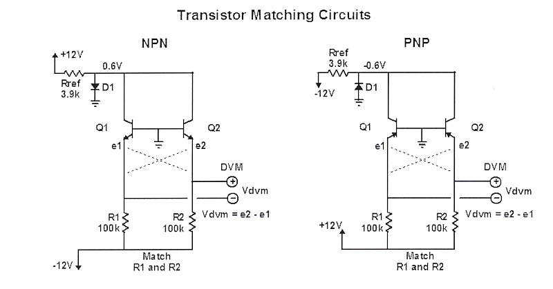
Ian Fritz Transistor Matching Circuit
R1 and R2 require extremely precise matching or trimming. When R1 and R2 are not trimmed, Ian describes a method of swapping the emitter leads and mathematically subtracting out the resistor match error to obtain delta-Vbe.
Even with R1 and R2 carefully matched or trimmed, their tempco, or the tempco of the trimmer becomes significant.
I decided to look for a method that did not require component matching which shared a common resistor and came up with the following:

A Commutating Chopper-Based Transistor Vbe Matcher
This is a proof-of-concept.
In the circuit above the transistors share a common emitter current sink resistor to eliminate the matching requirement.
The reference transistor, Q1 and the test transistor, Q2 are alternately switched on and off. I used 500 Hz.
When transistor Q1 is on and Q2 off, the base of Q1 is grounded and the emitter is at Q1's Vbe.
Let's assume transistor Q1's Ve is -600 mV.
When transistor Q2 is switched on it's Vbe will likely be different.
Q2's Ve may be -603 mV.
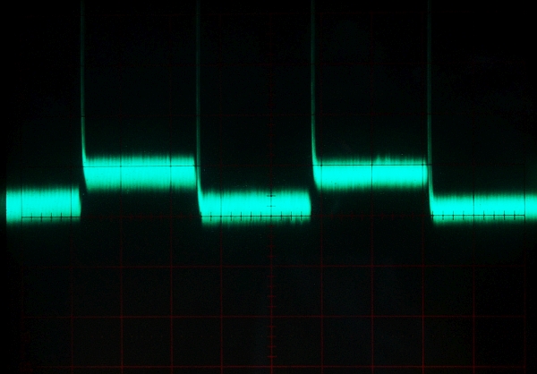
As the DG413 CMOS switches at the bases of Q1 and Q2 are toggled, an AC potential will be developed at the emitters whose peak-to-peak voltage will be equal to the delta-Vbe of the pair.
Switching the bases, rather than the emitters, reduces the effects of the DG413's RdsOn mis-match.
The output is read on a high gain AC-coupled oscilloscope.
There are two advantages to this method:
(1) The matching requirement and temperature drift of outboard resistors and trims are eliminated.
(2) The delta-Vbe can be read visually and very rapidly. Reading a moving target on a DVM is more difficult on a DVM than on a scope. As the measurement settles less interpretation is required.
A large mis-match is a high amplitude square wave - a close match has low amplitude.
There is some switching noise between Vbe pedestals which has to be visually ignored.
The 100K resistor, when combined with the 'scope probe and lead capacitance, form an RF low pass filter to prevent AM broadcast ingress and do introduce some measurement error of the peak-to-peak signal with a 1M scope input.
I mated up about 10 pairs of ZTX851 using this jig and also used it to check about half a dozen pairs I matched with Ian's jig.
The correlation between methods is pretty good.
A 'scope with a high vertical sensitivity is required without a preamp stage.
My 'scope has 5 mV/div with a X10 expansion so one division works out to be 500 uV/div.
Interesting observation is that ZTX851 tend to match up within 500 uV pretty easily.
When the Vbe is matched the Hfe tends to be pretty close too.
Updated 12/22/19:
This is the latest schematic for the Commutating Transistor Vbe Matcher.

A Commutating Transistor Vbe Matcher
More here: https://proaudiodesignforum.com/forum/p ... 420#p14420
Updated 10/8/20: viewtopic.php?f=6&t=1153&p=15635#p15635
Ian Fritz has come up with a really simple device that allows direct differential measurement and I've used it to match several batches of transistors.
Ian Fritz Transistor Matching Circuit
R1 and R2 require extremely precise matching or trimming. When R1 and R2 are not trimmed, Ian describes a method of swapping the emitter leads and mathematically subtracting out the resistor match error to obtain delta-Vbe.
Even with R1 and R2 carefully matched or trimmed, their tempco, or the tempco of the trimmer becomes significant.
I decided to look for a method that did not require component matching which shared a common resistor and came up with the following:
A Commutating Chopper-Based Transistor Vbe Matcher
This is a proof-of-concept.
In the circuit above the transistors share a common emitter current sink resistor to eliminate the matching requirement.
The reference transistor, Q1 and the test transistor, Q2 are alternately switched on and off. I used 500 Hz.
When transistor Q1 is on and Q2 off, the base of Q1 is grounded and the emitter is at Q1's Vbe.
Let's assume transistor Q1's Ve is -600 mV.
When transistor Q2 is switched on it's Vbe will likely be different.
Q2's Ve may be -603 mV.
As the DG413 CMOS switches at the bases of Q1 and Q2 are toggled, an AC potential will be developed at the emitters whose peak-to-peak voltage will be equal to the delta-Vbe of the pair.
Switching the bases, rather than the emitters, reduces the effects of the DG413's RdsOn mis-match.
The output is read on a high gain AC-coupled oscilloscope.
There are two advantages to this method:
(1) The matching requirement and temperature drift of outboard resistors and trims are eliminated.
(2) The delta-Vbe can be read visually and very rapidly. Reading a moving target on a DVM is more difficult on a DVM than on a scope. As the measurement settles less interpretation is required.
A large mis-match is a high amplitude square wave - a close match has low amplitude.
There is some switching noise between Vbe pedestals which has to be visually ignored.
The 100K resistor, when combined with the 'scope probe and lead capacitance, form an RF low pass filter to prevent AM broadcast ingress and do introduce some measurement error of the peak-to-peak signal with a 1M scope input.
I mated up about 10 pairs of ZTX851 using this jig and also used it to check about half a dozen pairs I matched with Ian's jig.
The correlation between methods is pretty good.
A 'scope with a high vertical sensitivity is required without a preamp stage.
My 'scope has 5 mV/div with a X10 expansion so one division works out to be 500 uV/div.
Interesting observation is that ZTX851 tend to match up within 500 uV pretty easily.
When the Vbe is matched the Hfe tends to be pretty close too.
Updated 12/22/19:
This is the latest schematic for the Commutating Transistor Vbe Matcher.
A Commutating Transistor Vbe Matcher
More here: https://proaudiodesignforum.com/forum/p ... 420#p14420