Bipolar Power Supply Load Current Imbalance And Transformer Core Saturation

Where we discuss new analog design ideas for Pro Audio and modern spins on vintage ones.
User avatar
mediatechnology
Posts: 5437
Joined: Sat Aug 11, 2007 2:34 pm
Location: Oak Cliff, Texas
Contact:

Re: Split Power Supply Load Balancing

Post by mediatechnology »

Image
WRT the Texar supply and load current imbalance:

I think I have a better idea of why a symmetrically-loaded transformer - producing more output power - is quieter when operating near its maximum rating than one when the load is imbalanced.

With no load on the negative rail the equivalent circuit looks like a full-wave center tap rectifier shown in the example above.
Current, some of it DC, returns through the center tap.

When both outputs are loaded equally there is no CT current.
The load is connected like the full-wave four diode bridge example above.
Current circulates from the positive output to the negative output; the equivalent circuit resembles a four diode full-wave bridge.

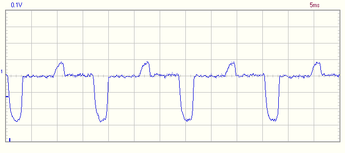
When the load current is balanced I can't measure DC in the secondary - only AC current.

Look at the table entry for "Transformer Secondary VA Rating" and compare the VA/PDC ratios for the FW CT rectifier and the four diode bridge.
For resistive loads the VA/PDC for the full-wave CT is 1.57 versus the 1.23 for the four diode FW bridge.
The FW CT configuration is far less efficient - it requires greater derating.
Accounting for DC may be the factor that increases the VA requirement for the FW CT topology.

Balancing the loads shifts the topology from one resembling a FW CT rectifier to that of a four diode bridge.
When operating as a four diode bridge efficiency is greater.
Not only does the transformer operate more efficiently there doesn't appear to be DC setup in the secondary.

Though its counter-intuitive increasing the load current - by loading the opposing output symmetrically reduced saturation in the Texar's marginal transformer VA rating.
In addition the marked increase in even-order and high-order harmonics points to bias - DC bias - in the core when the FW CT configuration is asymmetrically-loaded.

I remain convinced that if one supply has significantly higher current requirements that its better to use separate transformer secondaries and rectifier bridges.
Doing this will also reduce transformer VA requirements.
User avatar
mediatechnology
Posts: 5437
Joined: Sat Aug 11, 2007 2:34 pm
Location: Oak Cliff, Texas
Contact:

Re: Split Power Supply Load Balancing

Post by mediatechnology »

I ran another simple experiment since my last installment.

I placed a compass near the core of the power transformer and applied both an asymmetric load (FW-CT) and a balanced load (FW-Bridge).

The compass will deflect under application of load in the FW-CT configuration but not in the FW-Bridge mode.

The DC current measurements I've made aren't lying to me and assumptions about core magnetization seem to be confirmed by a compass needle.

So, in the case of the Texar supply and it's heavy LED load on the positive rail it appears that the transformer core is magnetically biased into saturation on half-cycles and that adding current to the negative rail pulls the operating point of the transformer core back into its linear region.

If the loads are nearly equal there's no DC in the core giving the transformer higher VA capacity and lower radiated harmonics.

In the case of the Texar, rather than burn off power, I opted to retrofit it with a switcher.
The unit is quieter and cooler now.
User avatar
terkio
Posts: 304
Joined: Thu Feb 07, 2019 3:17 am
Contact:

Re: Split Power Supply Load Balancing

Post by terkio »

Interesting studies, I get similar results calculating with LTSpice simulations.

I am thinking we have millions of center tap transformers used in line level audio.
Negative and positive rails are rarely equally loaded in those equipments.
It seems to me, nobody cares, nor has ever seen trouble, is that because transformers are generally oversized ?
Can we conclude from your study that we better equalise the two loads, adding a bleeding resistor ?
This wastes power but we have a better efficiency, may be this compensates, offering a free meal.
You mention "even" harmonics showing up when there is DC current. Isn't it odd harmonics of 60 Hz, namely 180 Hz, 300 Hz, 420 Hz,
The ripple in a perfectly balanced rectification has only even harmonics of 60 Hz, in other words this ripple is a 120 Hz signal.
User avatar
mediatechnology
Posts: 5437
Joined: Sat Aug 11, 2007 2:34 pm
Location: Oak Cliff, Texas
Contact:

Re: Split Power Supply Load Balancing

Post by mediatechnology »

terkio wrote: Sat Nov 14, 2020 9:48 am Interesting studies, I get similar results calculating with LTSpice simulations.

I am thinking we have millions of center tap transformers used in line level audio.
Negative and positive rails are rarely equally loaded in those equipments.
It seems to me, nobody cares, nor has ever seen trouble, is that because transformers are generally oversized ?
Can we conclude from your study that we better equalise the two loads, adding a bleeding resistor ?
This wastes power but we have a better efficiency, may be this compensates, offering a free meal.
You mention "even" harmonics showing up when there is DC current. Isn't it odd harmonics of 60 Hz, namely 180 Hz, 300 Hz, 420 Hz,
The ripple in a perfectly balanced rectification has only even harmonics of 60 Hz, in other words this ripple is a 120 Hz signal.
I'm glad sims back this up and I didn't simply imagine it. :lol:

I would venture to say that in many cases positive and negative supplies are fairly equally-loaded because there are auxiliary supplies for illumination, logic etc. and the bulk of the load on the bipolar rails are op amps. On my boards the slight load asymmetry I see is output Vos into load. That adds a tiny bit of current to one side.

I would hope that most transformers are adequately-sized for the job - it's only when they're on the edge and then the designer or user goes and adds a lot of illumination or relay load to the positive rail. It makes the argument that relay coils and LEDs should connect from the positive supply and return to the negative when there is no supply available for them and they're a large percentage of the load. In the case of the Texar this was not an option due to the use of LM3914 drivers.

I was tempted to add a bleeding resistor to the Texar's negative bulk supply and move on but it would have to be a fairly high wattage and the unit ran hot as it was. I do think the transformer would have run cooler but the positive regulator burns off quite a bit of heat and the resistor would have just added to it.

The harmonic content of the waveform I refer to is not the harmonic content of the ripple but the harmonic content radiated by the core. In the case of the Texar the DC rails looked clean. I got my first clue it was a field when the Texar I was powering externally was dead quiet but when the unmodified unit below it was switched on it got noisy again.

The Texar is particularly susceptible to this due to high internal impedances in the filters and Vactrol attenuators.

A "noisy" transformer radiating hum installed in gear might not make that particular piece noisy but it might cause its neighbor in the rack to hum. The finger of blame would usually get pointed to the gear with the hum, not the field its subjected to by the unit sitting right below it. The Texar messed up itself. I was honestly shocked by what I saw but after reflection wasn't surprised considering one of the first mods Gentner made was to switch from a flat-pack to a torodial transformer.

When the transformer of a FWCT is equally loaded on the positive and negative rails, making it a FW-Bridge, the transformer will show mild saturation at waveform peaks equally on both polarities.
When DC starts to develop in the core, due to load imbalance with DC in the CT, the operating Q-point of the core shifts due to magnetic bias so that one polarity "clips" sooner than the other.
The radiated asymmetric waveform becomes rich in even-order/high-order harmonics.

You can also see differences in waveform distortion at the secondary on positive vs. negative peaks. That's a clear indication of even-order products and DC in the core.
When the positive rail is loaded more it's peak is slightly lower in amplitude and has harder corners.
User avatar
mediatechnology
Posts: 5437
Joined: Sat Aug 11, 2007 2:34 pm
Location: Oak Cliff, Texas
Contact:

Re: Split Power Supply Load Balancing

Post by mediatechnology »

Before I cleaned this project off the workbench I wanted to grab a couple of oscillograms of secondary current under unbalanced (FW-CT) and balanced (FW-Bridge) load conditions.

I inserted a 1Ω sense resistor in series with one winding to indirectly measure current.

This is the secondary current with an unbalanced load.
The amplitude asymmetry about ground and the differing area under their curves shows us that a core-magnetizing DC component is being developed in the winding.
The DC robs us of VA capability two ways: It increases the wire current and if large enough biases the core out of its linear region.

Image
Supply Secondary Current Unbalanced Load

When the load is connected from the positive to negative output the rectifier is operating as a four diode bridge.
The current waveform is symmetrical about ground and has no core-magnetizing DC component.

Image
Supply Secondary Current Balanced Load
User avatar
terkio
Posts: 304
Joined: Thu Feb 07, 2019 3:17 am
Contact:

Re: Split Power Supply Load Balancing

Post by terkio »

Exactly the waveforms I get with simulations. And no need to insert 1 ohm resistors ;)

Actually there is no need for simulations nor measurements to figure that load imbalance induces DC at the CT.
The current load difference flows at the ground track at the loads. This current is near pure DC with some ripple. It comes from the CT with the capacitors on the ground track.
The current at the CT is far from pure DC, but has the same average value. That is because the current througt each capacitor has a 0 average value. Over an exact 60 Hz cycle, the capacitor voltages are the same, hence capacitor average currents are 0.
User avatar
mediatechnology
Posts: 5437
Joined: Sat Aug 11, 2007 2:34 pm
Location: Oak Cliff, Texas
Contact:

Re: Split Power Supply Load Balancing

Post by mediatechnology »

terkio: Thank you for running the sims.

I initially came to my conclusion that DC flows in the CT and saturates the transformer based on intuition and instinct.
It took one experiment.

To reduce the Texar's radiated hum the first thing I did was to counter-intuitively add load in the right place.

Did I base this on science, something I had read or any measurements?
I don't think so.
I did it because I felt it.
An inner voice spoke and the gut said "do this."
"We" were all in agreement.

A sim of this circuit leaves omits the most important detail: The effect of DC on the core and the harmonic distortion it creates in the radiated field.

To determine the presence or absence of DC in the core I cobbled up a test circuit, measured it, and documented the results to verify the accuracy of these three statements:
The single phase Full wave Center tap ( The middle diagram in the three ) driving one load.
(1) It makes no DC at the transformer. If it were, this widely used configuration would heat, the core saturate, eventually blow up.
(2) DC and spurious harmonics can occur only from a mismatch in the two rectifying legs. From diodes, windings, wiring, solder joints.
(3) Adding two diodes to drive a second load for an opposite polarity doesn't make any difference.
Maybe I was full of it - what do the measurements say?
Having the core pull a compass needle was extra fun - its what our ancestors would have done to prove the hypothesis.

When I proved to myself in my first experiment that load current imbalance was saturating the core I did a web search and came up with very little helpful information at all about DC saturating power transformers in split supplies.
I decided it might be a good idea to point out what I'd found.
User avatar
terkio
Posts: 304
Joined: Thu Feb 07, 2019 3:17 am
Contact:

Re: Split Power Supply Load Balancing

Post by terkio »

At the beginning of this discussion, I was confused, then used simulation to figure out what was going on.
4 diodes, 2x 10000uF caps with ESR 0.5 Ohm.
As a transformer 2 AC voltage sources, 18V peak with 1 Ohm resistance.
Loads 10 Ohm and 50 Ohm.
Then all became clear in my mind.
I am aware, this transformer substitute has no leak inductance, no core hysteresis, no saturation.

If this can be of interest, give me data, I can run a sim to give the calculated results.
User avatar
mediatechnology
Posts: 5437
Joined: Sat Aug 11, 2007 2:34 pm
Location: Oak Cliff, Texas
Contact:

Re: Split Power Supply Load Balancing

Post by mediatechnology »

It was clear in my mind from the beginning but I didn't know why. :lol:

I had to find out why my gut and instincts were telling me what to do.
You made me prove it - in hardware - and I learned something.

I'll stand by my original assertion that if a large imbalance in loads are expected its better to use separate secondaries (4 wires) and separate bridges (8 diodes) to avoid DC core magnetization and get the maximum VA out of the transformer.
The transformer will radiate a quieter field because its operating at its more linear center-point.

I'd be curious to find a source that just comes out and directly says that a FW CT rectifier will magnetize a transformer.
I am aware, this transformer substitute has no leak inductance, no core hysteresis, no saturation.
And the sim offers no way to probe its' field.
User avatar
terkio
Posts: 304
Joined: Thu Feb 07, 2019 3:17 am
Contact:

Re: Split Power Supply Load Balancing

Post by terkio »

mediatechnology wrote: Sun Nov 15, 2020 7:58 am I decided it might be a good idea to point out what I'd found.
Yes it is.
Your study is far more interesting than efforts I have seen on regulated PSU, aiming at sub microvolt noise, ripple reduction beyond 130 dB and output impedance in micro Ohms. :lol:
I'd be curious to find a source that just comes out and directly says that a FW CT rectifier will magnetize a transformer.
So do I.
Post Reply