
There have been many changes to the original 2006 input-capacitorless design to incorporate the THAT1570 and 5173 digital gain controller as well as improvements in servos, the power supply and many other details.
What remains the same is the basic principle of using "Flying Supply Rails" to eliminate the sometimes problematic high-value, high-stored-charge input coupling capacitors.
When I compare what it takes to build a conventional AC-coupled preamplifier to the "Input-Capacitorless" approach it becomes obvious that the primary difference between the two boils down to one circuit block: The common mode servo comprised of an op amp and two transistors. There are minor differences between the conventional and direct-coupled approaches: The 48V supply becomes 66 volts. If you want to control gain digitally using a THAT5173, four opto-isolators are required for the SPI lines. But that's about it. Almost all preamps require the basic blocks of input network, servo and final common mode rejection.
To make an input-capacitorless preamp we're not talking about adding many parts and in some cases we're just moving parts from one area to another...
The original thread is still here: https://www.proaudiodesignforum.com/for ... p?f=6&t=14
That thread is locked to prevent accidental posting of replies to this thread and avoid confusion.
Why eliminate the Input Coupling and Rgain Capacitors in an Active mic preamp?
1) Because I can; because it's out-of-the-box; because others said "it couldn't be done."
2) It eliminates the 48V Phantom Menace from stored charges.
3) It reduces low frequency 1/f noise because the reactance of the input capacitors that normally appear in series with the source impedance are eliminated. With the exception of required low-value current limiting resistors the preamp "sees" the microphone's source impedance.
4) It eliminates input capacitor electrolyte formation time, leakage current offsets and noise and gain switching clicks from "recharging" due to dielectric absorption.
5) It eliminates all electrolytic capacitors from the signal path.
6) It eliminates a very large Rgain capacitor.
7) There are only two capacitors in series with the signal path and both are low-value film.
I would caution the reader that this design remains a work in progress. The project remains on a Protoboard and some components required for stability might require change or removal once it's on a PC board.
"It can't be done. Microphones pull unequal current in each leg."
Many of the people that I've spoken with off-line about this approach have the knee-jerk reaction of "Well you can't DC-couple an input because microphones pull unequal current from each leg. That creates an offset." Though I've repeatedly addressed that issue let me say it once again early on: It has a servo for that. Though I'm sure someone will come up with some horrendous example of a current-imbalanced mic I've yet to find one it couldn't handle. I mention this early in the post because most professional designers I've spoken with tell me this is a deal-breaker for a fully DC-coupled preamp. I beg to differ.
The Direct-Coupled Input Capacitorless mic preamp has been tested with a modest number of condensor and dynamic microphones the most problematic of which was found to be the Behringer ECM8000 due to it's highly-imbalanced current offset of ~120 uA. (The IEC spec IIRC is about 4% imbalance. Note also that the ECM8000 comes with many different versions of internal electronics.) With the values shown in the following schematics the offset correction from the ECM8000s current imbalance used only about half the available servo correction range. That range could easily be made 5-10 times larger by making a couple of resistors lower. Transformer-coupled mics self-equalize their offsets due to the transformer's DC winding resistance. AC-coupled mics built to IEC specs also have well-balanced current draws. So to those people who insist on believing it still can't be done keep telling yourself that and I'll keep looking for something worse than an ECM8000.
What about phantom faults?
I've also tested this design with numerous phantom fault configurations and there has never been a single failure except for the test when I deliberately removed the phantom protection diodes. This test had a microphone connected with an internal transformer. Protection diodes are needed because there can be a stored charge (or inductive kickback) in the microphone itself. With diodes in place to protect the preamp from the microphone it's survived every test.
A brief discussion follows each image.The following is an overall Block Diagram.
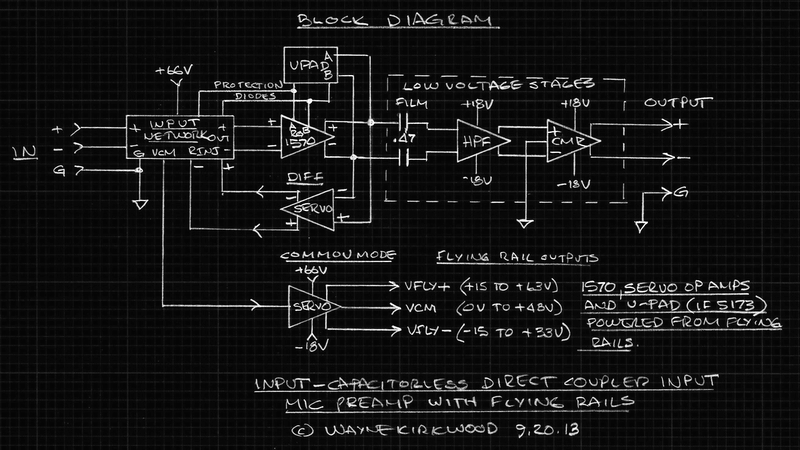
Input-Capacitorless Preamp Overall Block Diagram
This is the block diagram of the preamp showing how the individual elements combine into an overall system.
Input Network
The input network is fairly conventional with the exception that there are no input coupling capacitors.
Though there are no large-value electrolytic capacitors in the signal path, current limiting and phantom power protection are still provided since stored charges and inductance may exist in the microphone itself.
Differential servo correction voltages are applied to the input network to correct mic current and preamp offset errors.
A sample of the input DC common mode voltage, which for a phantom-powered mic is it's operating Q-point, is provided by the input network to feed the common mode servo and flying rail generator.
The input network feeds the 1570 inputs and Rgain connections.
The Common Mode Servo
A feed-forward common mode servo follows the DC Q-point voltage at the inputs and provides power supply rails that bracket the input DC common mode voltage (Vcm) by +/-15V.
The output of the common mode stage provides bootstrapped supply voltages for itself, the THAT1570, the differential servo and the THAT5173 U-pad digital gain controller.
The Vcm output of the Common Mode Servo is not used when gain is mechanically-switched.
The Differential Servo
The differential servo corrects the DC offset of the microphone which can occur due to unequal current draw as well as the offset of the THAT1570.
The correction range is approximately 240 uA when 100K injection resistors are used.
Injection resistor values as low as 10K have been tested.
U-Pad Gain Control
Gain control of the preamp is accomplished by a "U-pad."
The U-pad can be a pair of resistors along with a resistive stepped switch, potentiometer or a THAT5173 Digital Gain Controller IC.
The stepped switch approach uses fixed values of Ra and Rb. Rg is switched to provide gain values between 0 and +60 dB.
I also tested a stepped switch design that used a driven-shield cable to provide screening for the gain leads with reduced cable capacitance.
I have also tested the THAT5173 Digital Gain Controller using opto-isolated SPI control lines.
Opto isolation is required because the 5173 floats relative to CPU ground.
The 5173 circuits will be posted later in the thread.
Low-Voltage Stage, Highpass Filter
The floating differential output of the THAT1570 is AC-coupled using small-value film capacitors into a switchable "low-voltage" HP filter and optional +10 dB gain stage.
This stage and the ones following are isolated from the floating preamp and operate from conventional +/-18V ground-referenced supplies.
While the input-capacitorless preamp could be fully DC-coupled using a level-shifter to remove the approximate 30-48 volt potential this is unnecessary.
To begin with the differential servo also prevents operation to DC.
Plus there's almost always the need to remove sub-sonic content.
The low frequency cutoff of the AC-coupling stage is approximately 7 Hz. It could easily be made lower.
A switchable 40 Hz 12dB per octave high pass filter is also included using simple DPDT switching.
Common Mode Rejection Stage
The preamp carries AC common Mode signals from the input to the final stage with unity gain.
With the exception of bypass capacitors only three points touch ground: The input connector and network, the common mode rejection/line driver stage, and the output connector.
The common mode rejection stage removes common mode signals from the final output before being sent to the line driver stage.
The Input Network
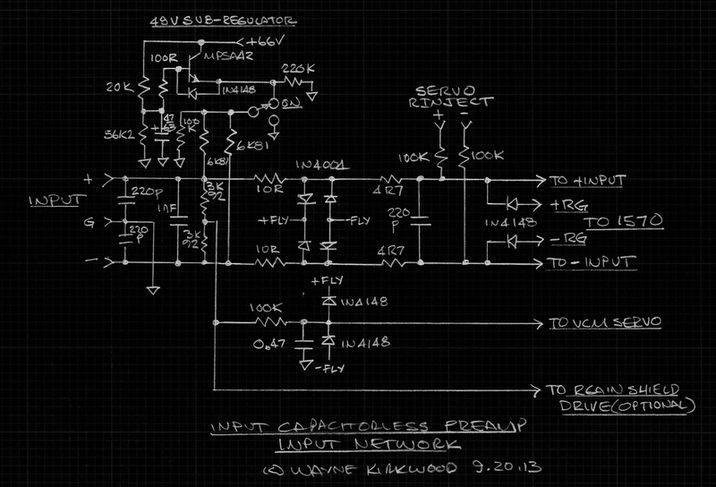
Input-Capacitorless Preamp Input Network
The input network is similar to the circuit published in THAT's DN-140 with one notable exception: There are no coupling capacitors.
48V Sub-Regulator
The +66V high voltage power supply is sub-regulated by an MPSA42.
The primary reason for this stage is to provide a low-noise capacitance multiplier that reduces the 66V supply down to 48V.
The 100R base stopper resistor is essential to prevent the emitter follower from oscillating.
The 220K pre-loads the regulator.
Phantom Pull-Up/Bias Resistors
The 6K81 phantom pull-up resistors provide current for the microphone and bias current for the THAT1570.
The preamplifier has a constant input impedance regardless of whether phantom is on or off due to back-grounding the off position.
During phantom switching, the 1570 is in T-bias with a 100K resistor returned to ground.
Differential Termination and Common Mode Sample Point
Two 3K92 resistors differentially terminate the input.
The center tap provides a sample of the common mode voltage.
The 5K input termination value (13K6||7K84) was chosen as a safe maximum for open input phantom faults (one leg shorted to ground) to keep the differential voltage within the common mode range of the preamp inputs.
Protection diodes eliminate the need for this voltage divider but values much higher than 5K are ultimately limited by the phantom resistors themselves at 13.6K.
5K was chosen arbitrarily and different values of differential termination can be used.
The 100K and 0.47 uF film capacitor integrate the input common mode signal to measure the DC Q-point voltage when phantom power is applied to the mic.
The tau of this network is 47 ms.
The output of the integrator feeds the common mode servo to provide the flying DC rails.
An optional output may be used to drive the Rgain cable shield - through a buffer - when mechanical gain switching is used.
Current Limiting, Common Mode Balance and Servo Injection Components
The 10 and 4R7 Ohm resistors along with 1N4004 and 1N4148 diodes provide current limiting and steering when phantom faults occur.
The resistors also serve as "base stopper" resistors for the 1570 inputs.
Series resistance also appears to reduce imbalance from the 220 pF input (common mode) RFI filters and 1N4004 junction capacitances.
I've not performed phantom fault testing with values below 10R, but I believe they might be lowered to 4R7 to minimize source impedance seen by the 1570 from about 30R to 20R plus source Z.
The inductance of the 1 nF differentially-connected input capacitor is also isolated by the 10 and 4R7 resistors.
This one was a surprise. During testing it was found that if a 1 nF were connected directly at the 1570 input pin without series resistance the 1570 would internally oscillate in the 10-20 MHz region with certain types of capacitors but not others.
It would manifest itself in the audio region as noise and reduced CM rejection.
Wrapped film capacitors caused intermittent oscillation, stacked film or MLC caps did not.
The inductance of the capacitor likely has a role in this effect and it was discovered that the sensitivity to it was reduced by moving it to the left of the input series resistors.
Both the 220 pF (at the 1570 input) and the 1 nF near the connector should have low inductance construction.
The two 100K servo "injection" resistors convert the Differential Servo output voltage to current to correct offset errors from the microphone and THAT1570.
To increase servo correction range these resistors can be made lower.
Initial tests with the 1510 circuits used 10K injection resistors but I raised them to 100K since I do not have a mic sample that justifies them being that low.
The Common Mode Servo and Flying Rail Supply
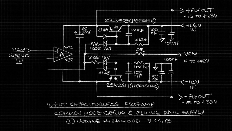
Input-Capacitorless Preamp Feed-Forward Common Mode Servo With Bootstrapped Flying Rail Supply
What The Common Mode Servo Does
The feed-forward Common Mode Servo provides bootstrapped flying rail power supplies for itself, the THAT1570 preamp, Differential Servo and the optional THAT5173 Digital Gain Controller that are bracketed +/-15V from the operating Q-point of the microphone.
When phantom is off, VFLY+ is +15V; VFLY- is -15V.
When Phantom is on, and no microphone loading the current sourcing resistors, VFLY+ is +63V; VFLY- +33V.
When Phantom is on and the microphone is loading the current sources to provide a Q-point Vcm of 30V, VFLY+ is +45V; VFLY- is +15V.
The difference between VFLY+ and VFLY- is always 30V.
The flying rail supply makes certain that the common mode voltage range of the THAT1570 and support circuits are not exceeded.
The Vcm "pseudo-ground" output of the Common Mode Servo is only connected when a THAT5173 Digital Gain Controller is used.
The THAT5173 requires a ground connection and a Vdd supply that is 3.3V greater than it's ground pin.
With a gain controller in use the floating Vcm supply drives analog and digital "ground" and the reference connection for the 3.3V Vdd supply.
The THAT1570 and Differential Servo require no ground or Vcm connection.
A 100 uF capacitor is connected between VFLY+ and VFLY-.
The 100 uF is bootstrapped and has a constant 30V potential across it.
A large-value capacitor is used to absorb any stored charge steered into it by the input network's protection diodes.
Although the preamp itself contains no large-value electrolytics in the signal path that might have a stored charge, the microphone ahead of it might.
The Differential Servo

Input-Capacitorless Preamp Differential Deboo Integrator Servo
A Differential Servo Is Required to Correct The Microphone's DC Offsets
A Differential Servo is required to prevent the current imbalance of the microphone and voltage offsets of the THAT1570 from being multiplied by the gain of the preamp.
Conventional mic preamps that do not have a Cgain capacitor usually require servo correction of preamp input offsets.
Without a servo a 1 mV input error multiplied by the 60dB gain of the preamp would result in 1V offset at the output. Stepped gain changes would click horribly.
The input-capacitorless preamp simply uses the same servo to correct input error regardless of whether it's produced by the microphone or preamp.
The servo senses the output differential DC voltage error and provides a correction signal back to the input in the form of a current.
A differential form of the Deboo Integrator was developed.
The Deboo has the advantage of having a passive pole at the input and being non-inverting.
The passive pole reduces the bandwidth requirements of the servo op amp and allows the use of low-cost, DC-precise, low offset, low bias current parts.
Because the Deboo integrator is non-inverting, the outputs of the 1570 and servo cross-couple to the 1570 inputs.
The "+" 1570 output through the servo feeds the "-"1570 input.
A comparison of the Differential Deboo to the 5173's internal servo the Deboo slightly outperformed it because it has less DC error, and for a given value of Rinjection, more range.
For whatever reason the Deboo provided correction with an output more evenly "split" between inputs.
The Low-Voltage High Pass Filter and Common Mode Rejection Stage

Input-Capacitorless Preamp High Pass Filter and Double-Balanced Common Mode Rejection Stage
This stage is powered by conventional +/-18V supplies.
Why is the preamp not fully DC-Coupled?
The input-capacitorless preamp is not fully DC-coupled because no one really needs DC response.
The objective was to eliminate the input coupling capacitors and a large "Cgain" capacitor, not all capacitors.
A servo eliminates Cgain and prevents response to DC.
The floating outputs from the THAT1570 range from -0.7 to +48VDC and are AC-coupled to the following stages.
The preamp has only two 0.47 uF film caps in the primary signal path.
There are no electrolytic capacitors in the path at all.
Differential AC-Coupling
100R input resistors and clamp diodes limit peak current as phantom is switched on or off.
The stored charge in these capacitors 1/100th the charge of a conventional preamp's 47 uF (or greater) input coupling capacitors.
The left-hand 0.47 uF film caps isolate the DC component in the 1570 output from the following low-voltage stages.
These capacitors work into a ~100K differential load.
"T-bias" provided by the 1M resistor to ground provides a high common mode impedance to minimize capacitor matching requirements and improve LF common mode rejection.
The noise and DC bias current potential developed across the 1M resistor appears in common mode at the output and is rejected by the following stage.
The common mode gain of this stage is "1"
Common mode signals pass through the input preamp and this AC-coupled differential stage essentially unaltered.
Instrumentation Amplifier with 10 dB Gain
An LME49860 dual op amp is connected as an instrumentation amplifier to provide either unity or +10 dB gain for use with low output (ribbon) mics.
The LME49860 is an excellent choice due to its' low bias current and other attributes.
A 5532 in this circuit also performs well though its bias current develops a significant common mode potential across the 1M T-bias resistor.
Instrumentation Amplifier with 40 Hz High Pass FIlter
When the HP filter is engaged, two additional 0.47 uF capacitors are switched in and the differential impedance at the instrumentation amp input is reduced to 24K by the 31K6 resistor. (99K8||31K6).
This converts the stage to a differential 2 pole "unity gain" Sallen-Key HP filter having a 40 Hz cutoff.
The 12K feedback resistors for the Sallen-Key filter are taken from the inverting input so that the gain of the instrumentation amp appears to be unity even when it is +10 dB.
When the filter is switched out, the 12K resistors are bootstrapped across the op amp inputs and are effectively out of the circuit; the right-hand pair of 0.47 uF film caps are shunted by the switch.
Though somewhat unconventional this arrangement saves components.
Common Mode Rejection
The output of the high pass filter is fed to a pair of "Double-Balanced" cross-coupled THAT1246 line receivers.
Until this stage common mode signals have passed through the preamp essentially unaltered at unity gain.
The pair of THAT1246 provide common mode rejection for the entire preamp.
The output of the Common Mode Rejection Stage is buffered by line drivers which are not shown.
Simple HV Power Supply From a 36VCT Transformer

Input-Capacitorless Preamp Bootstrapped Power Supply
The preamp uses simple rectification and bootstrapping to provide a 66V supply.
These same components would be used to derive a 48V supply so there is no added complexity.
Note that the HV bridge is AC-coupled to the transformer and that it is bootstrapped by the bulk positive supply.
The +/-18V regulators are not shown.
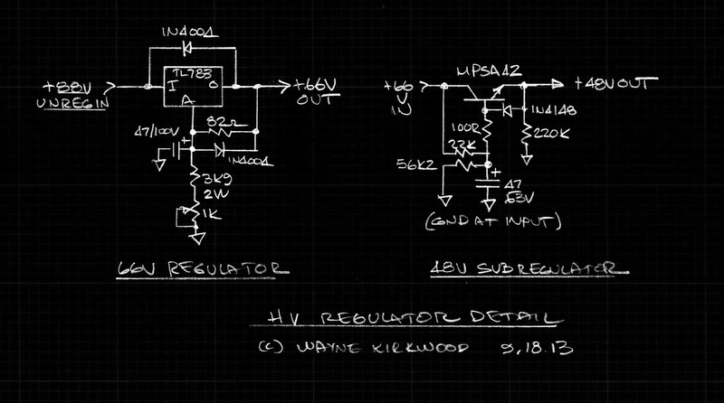
Input-Capacitorless Preamp High Voltage Regulators
The 66V supply is made from a TL783 regulator.
The 48V sub-regulator is on the input network and is referenced to the input connector pin 1 ground.
In a follow-up post I'll show how to integrate the THAT5173 Digital Gain Controller using Opto-Isolated SPI control lines.
You can jump to the gain controller post here: https://www.proaudiodesignforum.com/for ... 98&start=7
