My recent exploration of the Neuman VAB-84 Elliptic Equalizer served as the inspiration for the dedicated Stereo Width Controller shown here.
Update July 13, 2021: A new Width Controller is described here: viewtopic.php?f=6&t=681#p16479
This thread is the technical discussion. If you're looking for the construction thread to build the Stereo Width Controller it's here: http://www.proaudiodesignforum.com/foru ... ?f=7&t=731
This circuit does not use the "Mid" channel of Mid/Side or "MS" techniques.
I call it the "LR+/-S" method.
Updated the drawing 11-19-2014 and modified the description.
Schematic of the LRS-1 Stereo Width Control Using the LR+/-S Method
The core circuitry of the LRS-1 Width controller is IC3, IC6, IC8 and IC9.
THAT1246 balanced line receivers along with THAT1646 outputs provide both buffering and balanced inputs and outputs.
Like any of the matrices using differential line receivers it is important that the driving source impedance is an op amp output.
If the source is not buffered, the source impedance becomes part of the matrix and degrades its accuracy.
The balanced inputs provide the low source impedance required by IC3, IC8 and IC9.
THAT1646 output stages provide L and R balanced outputs.
IC3, a THAT1240, provides a Side signal that is that is equal to (L-R).
(A 1246 was originally used for IC3 to provide the needed (L-R)/2 signal but to maintain signal level at the insert send a unity gain THAT1240 was used and attenuation added at IC7.)
IC4 and IC5 provide an external Side Insert with RY1 providing bypass.
A low pass filter in the external Side Insert makes the circuit become an Elliptic Equalizer for vinyl mastering providing low frequency crossover to mono.
IC6, a THAT1240, along with a 10K linear potentiometer (or stepped switch) create a Side signal with a voltage gain, "k," that ranges from -1 to 0 to +1.
This permits Side to be subtracted or added to Left and Right.
100K resistors bridging the wiper of the pot to both ends of the pot provide bias current return for the THAT1240 input if the wiper lifts during rotation or switching.
If a stepped switch is used, Goldpoints are supplied in make-before-break and the 100K's can be removed to increase taper accuracy.
RY2 defeats the Width circuit for signal comparison.
IC7 attenuates the Side signal by a precise -6dB to provide a k{(L-R)/2} output.
THAT1240 summation stages IC8 and IC9 either add or subtract Side from Left and Right.
The Side signal at the output of IC7 is subtracted from L and added to R.
"Side" is evenly distributed between Left and Right but has opposite polarities.
Thus, Left contains a side component that is L + 0.5(side).
Right has a R -0.5(side) component.
If k=1 (IC6 is not inverting polarity) and the attenuation of IC7 is 0.5 then:
L = L +0.5(side) -0.5(side) = L
and
R = R -0.5(side) +0.5(side) = R.
Thus with no Side signal to make it stereo, L then equals R and the resulting signal is mono.
Obtaining mono is a subtractive process.
If k=0 then:
L= L +0.5 side
and R = R -0.5 side.
The result is normal stereo.
If k=-1 (IC6 is providing polarity inversion) and and the attenuation of IC7 is 0.5 then:
L = L +0.5(side) +0.5(side) = L + side
and
R = R -0.5(side) -0.5(side) = R - side.
Thus the amount of side in left and right are doubled relative to normal stereo where the side terms are +0.5 and -0.5.
Expanding width, or the side component, is an additive process.
The X-Y diagrams below show how the diagonal side axis is either fully collapsed to produce mono or doubled in width relative to normal stereo to expand width.
The following are X-Y Oscilloscope photos with 1 kHz applied to the Left channel and 10 kHz applied to the right.
When the polarity flipper's output is 0V, the Left/Right inputs are unprocessed and provide a "normal" stereo image.
A Stereo Width Control Using the +/-S Method, 1 kHz Left, 10 kHz Right, Set for Mono.
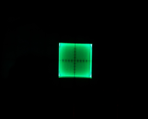
A Stereo Width Control Using the +/-S Method, 1 kHz Left, 10 kHz Right, Set for Stereo.
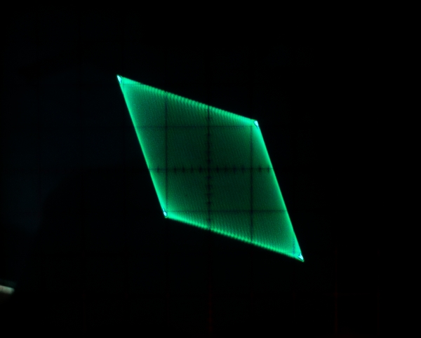
A Stereo Width Control Using the +/-S Method, 1 kHz Left, 10 kHz Right, Set for Wide.
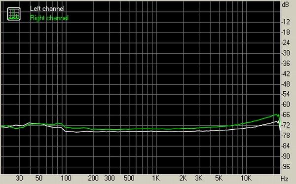
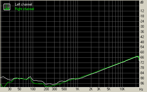
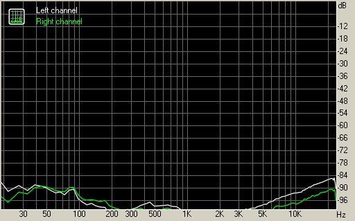
With the Width control centered crosstalk is excellent.
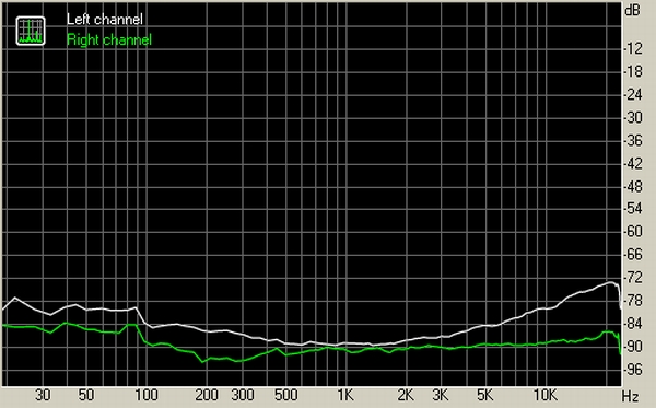
With the Width control bypassed, crosstalk is essentially that of the sound card used to perform the measurement.
I hope to have a dedicated PC board for this soon.
Read more about the VAB-84 "EE-84" Elliptic Equalizer here: viewtopic.php?f=6&t=622
See an earlier version of the Width control using a dual pot here: viewtopic.php?f=6&t=71&p=516
Stereo Width Control For Mastering Using the LR +/-S Method
- mediatechnology
- Posts: 5469
- Joined: Sat Aug 11, 2007 2:34 pm
- Location: Oak Cliff, Texas
- Contact:
Re: Stereo Width Control For Mastering Using the +/-S Method
Thanks
Best,
Doug Williams
Electromagnetic Radiation Recorders
Doug Williams
Electromagnetic Radiation Recorders
Re: Stereo Width Control For Mastering Using the +/-S Method
Great! Can't wait to see it.
- mediatechnology
- Posts: 5469
- Joined: Sat Aug 11, 2007 2:34 pm
- Location: Oak Cliff, Texas
- Contact:
Re: Stereo Width Control For Mastering Using the +/-S Method
Thanks everyone.
We spent 4 days on generator power and I'm just getting back into electronics work and replying.
Re: Stereo Width Control For Mastering Using the +/-S Method
mediatechnology wrote:Thanks everyone.
We spent 4 days on generator power and I'm just getting back into electronics work and replying.
???? I thought Dallas/FW had things like indoor plumbing, etc <g>.
Bri
Professional audio and video systems design/installation/maintenance.
www.BrianRoth.com
www.BrianRoth.com
- mediatechnology
- Posts: 5469
- Joined: Sat Aug 11, 2007 2:34 pm
- Location: Oak Cliff, Texas
- Contact:
Re: Stereo Width Control For Mastering Using the +/-S Method
I'm putting the finishing touches on the layout for the LRS_1 Width Controller.
Updated the drawing 11-19-2014 and modified the description.
Schematic of A Stereo Width Control Using the +/-S Method
Updated the drawing 11-19-2014 and modified the description.
Schematic of A Stereo Width Control Using the +/-S Method
- mediatechnology
- Posts: 5469
- Joined: Sat Aug 11, 2007 2:34 pm
- Location: Oak Cliff, Texas
- Contact:
Re: Stereo Width Control For Mastering Using the LR +/-S Met
Just got the LRS-1 Stereo Width Controller boards in:
LRS-1 Stereo Width Controller PC Board
The Width Controller uses a single 10K linear pot or stepped switch to pan from mono at CCW, to Normal Stereo at the mid-point, to twice normal width at the CW end.
The left and right inputs are fully balanced and an external Side insert point, also fully-balanced, is available for additional processing or high-order >=6dB/octave elliptic equalization.
Both Width and the Insert are relay-bypassed.
The layout performed flawlessly.
I'll be offering an assembled and tested board and two additional bare boards out of the first run.
https://www.ka-electronics.com/kaelectr ... _Width.htm
- mediatechnology
- Posts: 5469
- Joined: Sat Aug 11, 2007 2:34 pm
- Location: Oak Cliff, Texas
- Contact:
Re: Stereo Width Control For Mastering Using the LR +/-S Met
RMAA Test Results:
Width Control Centered
LRS-1 Width Controller Crostalk with Width Control Centered (normal stereo)
Full RMAA report for the LRS-1: http://www.ka-electronics.com/kaelectro ... ntered.htm
Width Controller Bypassed (Side Muted)
LRS-1 Width Controller Crostalk with Width Control Bypassed (side muted)
Full RMAA report for the LRS-1: http://www.ka-electronics.com/kaelectro ... passed.htm
Product web page for the LRS-1 Width Controller: http://www.ka-electronics.com/kaelectro ... _Width.htm
- mediatechnology
- Posts: 5469
- Joined: Sat Aug 11, 2007 2:34 pm
- Location: Oak Cliff, Texas
- Contact:
Re: Stereo Width Control For Mastering Using the LR +/-S Met
I was asked to explain the math behind the LR+/-S Method.
Schematic of A Stereo Width Control Using the +/-S Method
Stereo Width Controller “L/R ± S” Equations
Definitions
L is Left, R is Right, M is Mid, S is Side. “k” is a gain scaler for Side ranging from -1 to +1.
L + R = M
L - R = S
∴
L = 0.5M + 0.5S
R = 0.5M – 0.5S
Width Controller
S = Lin-Rin
k = -1 ≥ 0 ≤ 1 (Width Control.)
Lout = Lin + k(0.5S)
Rout = Rin – k(0.5S)
When k = 0 there is no added processing of Side.
∴
Lout = Lin
Rout = Rin
When k = -1 the output is Mono. The Side gain is 0.
Lout = Lin – 0.5S
Rout = Rin + 0.5S
Lout = (0.5M + 0.5S) – 0.5S
Rout = (0.5M – 0.5S) + 0.5S
Lout = 0.5M
Rout = 0.5M
Lout + Rout = M
Lout – Rout = 0
When k = 1 the image is widened. The Side gain is 2.
Lout = Lin + 0.5S
Rout = Rin – 0.5S
Lout = (0.5M + 0.5S) + 0.5S
Rout = (0.5M – 0.5S) – 0.5S
Lout = 0.5M + S
Rout = 0.5M – S
Lout + Rout = M
Lout – R out = 2S
Effect of “k” on Side gain.
When k = -1 the Side Gain is “0.” The gain in dB is -∞.
When k = 0 the Side Gain is “1.” The gain in dB is 0.
When k = +1 the Side Gain is “2.” The gain in dB +6.
Response to Input Conditions.
Single Channel Modulation. Left Channel with 1 unit of input.
Lin = 1
Rin = 0
∴
M = 1
S = 1
When k = -1 the output is Mono. The Mid gain is 1. The Side gain is 0.
Lout = (0.5M + 0.5S) + k(0.5S)
Rout = (0.5M – 0.5S) – k(0.5S)
Lout = 0.5 + 0.5 – 0.5
Rout = 0.5 - 0.5 + 0.5
Lout = 0.5
Rout = 0.5
Lout + Rout = 1
Lout – Rout = 0
When k = 1 the image is widened. The Mid gain is 1. The Side gain is 2.
Lout = (0.5M + 0.5S) + k(0.5S)
Rout = (0.5M – 0.5S) – k(0.5S)
Lout = 0.5 + 0.5 + 0.5
Rout = 0.5 – 0.5 – 0.5
Lout = 1.5 (Lout is +3.52 dB higher than Lin.)
Rout = -0.5 (Rout is -6 dB lower than Lin. Rout has inverted polarity.)
Lout + Rout = 1 (Mid gain is unity.)
Lout – Rout = 2 (Side gain is 2.)
The mono sum, “Mid,” has a gain of 1 regardless of the value of k.
The difference, “Side,” has a gain from 0 to 2 when k is varied from -1 to +1.
Both channels modulated with 1 unit of input. (Mono.)
Lin = 1
Rin = 1
∴
M = 2
S = 0
When k = -1 the output is Mono. The Side gain is 0.
Lout = (0.5M + 0.5S) + k(0.5S)
Rout = (0.5M – 0.5S) - k(0.5S)
Lout = 1 + 0 – 0
Rout = 1 – 0 + 0
Lout = 1
Rout = 1
Lout + Rout = 2
Lout – Rout = 0
∴
Lout = Lin
Rout = Rin
When k = 1 the image is widened. The Mid gain is 1. The Side gain is 2.
Lout = (0.5M + 0.5S) + k(0.5S)
Rout = (0.5M – 0.5S) - k(0.5S)
Lout = 1 + 0 + 0
Rout = 1 – 0 - 0
Lout = 1
Rout = 1
Lout + Rout = 2
Lout – Rout = 0
∴
Lout = Lin
Rout = Rin
Mono Inputs produce Mono Outputs regardless of the Width setting.
Both channels modulated without correlation and with 1 unit of input.
Lin = 1
Rin = -1 (Right input is polarity reversed for zero signal correlation.)
∴
M = 0
S = 2
When k = -1 the output is Mono. The Side gain is 0.
Lout = (0.5M + 0.5S) + k(0.5S)
Rout = (0.5M – 0.5S) – k(0.5S)
Lout = 0 + 1 - 1
Rout = 0 -1 + 1
Lout = 0
Rout = 0
Lout + Rout = 0
Lout – Rout = 0
The mono sum of inputs having no correlation is 0.
When k = 1 the image is widened. The Mid gain is 1. The Side gain is 2.
Lout = (0.5M + 0.5S) + k(0.5S)
Rout = (0.5M – 0.5S) - k(0.5S)
Lout = 0 + 1 + 1
Rout = 0 - 1 - 1
Lout = 2 (Lout is +6 dB higher than Lin.)
Rout = -2 (Rout is +6dB higher than Rin.)
Lout + Rout = 0 (Mono cancellation.)
Lout – Rout = 4
(Lout – Rout)/(Lin – Rin) = 2
- mediatechnology
- Posts: 5469
- Joined: Sat Aug 11, 2007 2:34 pm
- Location: Oak Cliff, Texas
- Contact:
Coming Soon: A New Stereo Width Controller For Mastering Using the LR +/-S Method
After many requests I've decided to reintroduce a simplified Stereo Width Controller PC board.
The board is only 2" x 4".
I've got a pre-production run on order.
New Stereo Width Controller Using the LR +/-S Method
I'll post schematics soon.
The board is only 2" x 4".
I've got a pre-production run on order.
New Stereo Width Controller Using the LR +/-S Method
I'll post schematics soon.