Thanks Hans for checking the sims and the FFTs of motor on/off.
I re-checked some measurements yesterday using the Phono Transfer System RIAA EQ board with the ZTX851 MC preamp.
I did this to allow me to switch between flat and RIAA EQ and trim out the insertion loss from A/D loading of the final output.
With an Rsource of 10Ω and an overall gain of 68 dB I'm still measuring an Ein of almost exactly -141 dBu.
That works out to a total Rnv of 14.5Ω.
Rsource plus Rgain is 11Ω leaving 3.5Ω for both transistors or approximately 1.75Ω rbb' each.
-141 dBu Ein over a 20 kHz BW works out to be about 0.48nV√Hz.
These numbers are consistent with what I measured earlier.
I'm not sure how AudioTester handles the bandwidth of its level calculations.
If I apply a second-order LPF to the input (in AudioTester) it's not reflected in the level measurements only the plotted FFT.
The bandwidth setting in the Analyze dialog only affects noise calculations for THD measurement, not level.
The Weighting filters can be reflected in the level measurements but there isn't one defined for noise measurement. (i.e. a 1,2 or 3rd order LPF.)
I need to figure out how to define a "User" filter.
So I can't tell you what the bandwidth is for level measurements but it must be pretty close to 20 kHz or the sims and measurements wouldn't be within the 0.5 to 1.5 dB that they are.
At this point its so much quieter that the DL-103's 40Ω||100Ω termination that if I'm off by a dB I'm way past caring.
Trying to hear the noise or hum floor at these levels while playing a record is risking one's hearing, monitors and may be death defying.
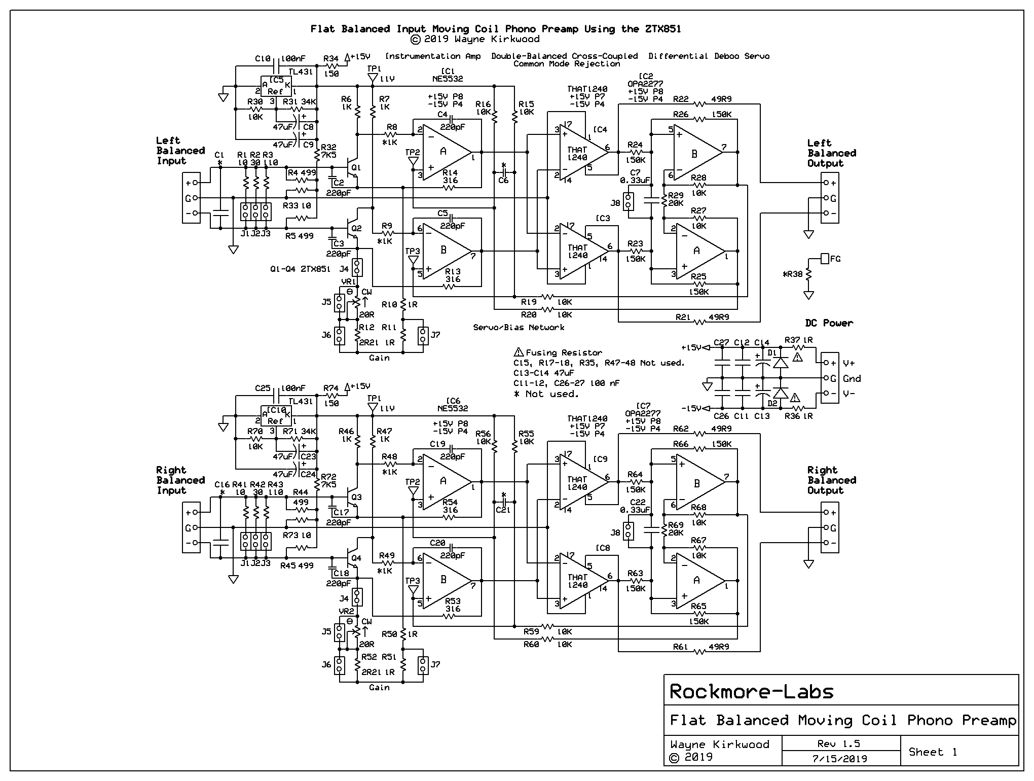
A Low Noise Balanced Input Moving Coil Preamp Using the ZTX851
-
mediatechnology

- Posts: 5453
- Joined: Sat Aug 11, 2007 2:34 pm
- Location: Oak Cliff, Texas
- Contact:
-
mediatechnology
- Posts: 5453
- Joined: Sat Aug 11, 2007 2:34 pm
- Location: Oak Cliff, Texas
- Contact:
Re: A Low Noise Balanced Input Moving Coil Preamp Using the ZTX851
Hans - Were you in a 60 Hz country?Hans wrote: ↑Wed Jul 03, 2019 7:36 am Wayne,
It's always nice to compare things.
Image below shows noise with Cart on the Platter with motor off, resp with motor on but belt removed recorded with my Diff in Diff Out preamp.
Image was originally made after Riaa correction, but with Audacity an inverse Riaa was applied, so noise above 10kHz is unreliable and should be flat.
HansMotor-on-off.jpg
Re: A Low Noise Balanced Input Moving Coil Preamp Using the ZTX851
That 120Hz spike is odd given Hans is firmly in 50Hz land.
-
mediatechnology
- Posts: 5453
- Joined: Sat Aug 11, 2007 2:34 pm
- Location: Oak Cliff, Texas
- Contact:
Re: A Low Noise Balanced Input Moving Coil Preamp Using the ZTX851
That's what I thought too.
120 Hz strobe signal?
FWIW my tests were run with the SP-15 platter off.
Running, or off doesn't make much difference though.
Re: A Low Noise Balanced Input Moving Coil Preamp Using the ZTX851
Yes, definitely 50 Hz, but 120 Hz is what I get with the Cart on the Platter.
With the Cart up in the Air, it’s completely gone, so it’s not an electro magnetic interference.
But there is a highway 1 Km away, and I suspect that this must cause some ground vibration, because in the middle of the night with no traffic, it’s gone

Hans
Re: A Low Noise Balanced Input Moving Coil Preamp Using the ZTX851
Wayne,
I have played a bit further with my Sim model with the adjusted Rb=1.5 Ohm for the ZTX851.
Short circuiting C7 and reducing R19/R20 from 10k to 1K Ohm, resulted in -140.23 dBu RTI with 20 KHz BW.
So my question is, what values for R19/R20 are you using, since 10K seems a bit large, also doubling the phase shift at 20kHz from 6 to 12 degrees.
-140.23dBu@20 KHz is 0.535nV/rtHz corresponding to 17R17.
Subtracting 11R leaves 6R17 for the two transistors or 3R09 per transistor (when accounting all noise exclusively to both input transistors and the 10R +1R).
With Ic=10mA, Rbb calculates as (3R09-1/2gm) = (3R09-1R25)= 1R84
This calculated Rbb=1R84 corresponds quite nicely with Rb=1R5 in the Spice model.
Hans
Re: A Low Noise Balanced Input Moving Coil Preamp Using the ZTX851
With the calculated -140.23 dBu, S/N after Riaa and A-weight is 83.7 dBA including Rs=10Ohm.
This is ca 1/250 in noise power below the surface noise from an LP !
Hans
This is ca 1/250 in noise power below the surface noise from an LP !
Hans
Re: A Low Noise Balanced Input Moving Coil Preamp Using the ZTX851
That S/N calculation was for a Cart producing 0.5mV@5cm/sec/1KHz.
For a 0.25mV Cart, S/N becomes 77.7dBA.
Hans
For a 0.25mV Cart, S/N becomes 77.7dBA.
Hans
-
mediatechnology
- Posts: 5453
- Joined: Sat Aug 11, 2007 2:34 pm
- Location: Oak Cliff, Texas
- Contact:
Re: A Low Noise Balanced Input Moving Coil Preamp Using the ZTX851
Hans -
I'm using 10KΩ for R15-R16 and R19-R20.
If they were scaled lower a lot of current would be pulled out of the 11V supply.
Short C7?
Do you mean C6?
Not sure what you mean about phase shift at 20 kHz.
Both C6 and C7 are in the servo.
C6 is a HF bypass for the servo control point and isn't part of the integrator time constant.
Re: A Low Noise Balanced Input Moving Coil Preamp Using the ZTX851
Bringing R19-R20 to 1K was the only way to get noise RTI at -140dBu, that's all I tried to tell.
And indeed, Collector current for both ZTX851 goes in that case from 5.5 mA to 10 mA, not really shocking I think, because at the same time dissipation in both transistors goes from 33mW to 16mW.
The images below show the FR for both situations, where phase-shift at 20Khz improve from 12 to 6 degrees.
It was just some playing around with LTSpice, but of course it's all up to you, use the information for what it is.
Hans