A Second Order Elliptic Equalizer for Vinyl Mastering

Where we discuss new analog design ideas for Pro Audio and modern spins on vintage ones.
User avatar
mediatechnology
Posts: 5437
Joined: Sat Aug 11, 2007 2:34 pm
Location: Oak Cliff, Texas
Contact:

Re: A Second Order Elliptic Equalizer for Vinyl Mastering

Post by mediatechnology »

Using an Allpass filter in Mid to compensate for the phase response of the Side HPF allows symmetric second-order 12 dB/octave Elliptic Equalizer response and eliminates peaking.

Image
Elliptic equalizer response using MS. Side is HPF, Mid is Allpass filter. Red is lateral, Blue Vertical, Green Left, Violet Right.

The Side filter cutoff is just above 300 Hz. (Difference between Red and Blue curves.)
The Vertical and Crosstalk slopes are both 12 dB/octave despite the subtractive/derived response of crosstalk.
There is no peaking in Vertical, Left or Right.
The Lateral Mono sum is unity.

The rising response in the right channel above 5 kHz may be layout-related or some slight phase error in the voltage followers.

I'll post a schematic of the filters which are super-simple.
User avatar
mediatechnology
Posts: 5437
Joined: Sat Aug 11, 2007 2:34 pm
Location: Oak Cliff, Texas
Contact:

Re: A Second Order Elliptic Equalizer for Vinyl Mastering

Post by mediatechnology »

Schematic for a second-order 12 dB/octave Elliptic Equalizer with allpass correction in the Mid channel.

Image
Mid Side Elliptic Equalizer With Second Order Allpass Correction Filter

The filter is designed to be inserted between an MS Encode and Decode stage.

The Side filter is second-order 12 dB/octave made from cascaded 6 dB/octave sections.

The primary motivation for using two sections was to make the filter resistors, which will likely be controlled by a multi-pole stepped switch, equal value.
In addition it was thought that two single-order sections would more accurately follow the two cascaded single-order allpass response.
The response of the two cascaded 6dB per octave stages are also guaranteed monotonic.
The Fc of each individual section should be approximately 0.64 the desired EE frequency; for 300 Hz EE the two cascaded sections should be tuned to 192 Hz.

Resistors R9 and R10 prevent latch-up of the filter voltage followers.
(Bipolar input op amps having diodes between the inputs, as well as some FET input op amps, require current limiting to prevent latchup.)

The resulting Vertical crossover slope is 12 dB/octave.
With the 8K25Ω resistors shown, the Vertical cutoff frequency is about 300 Hz.

The Mid section is a second-order allpass network made from two cascaded single-order sections.

The phase shift of an allpass filter is twice that of an equivalent high pass filter or that of the network located in the noninverting input.
For the phase response of the Mid allpass filter to equal that of the Side's HP filter, its cutoff frequency must be an octave lower.
To scale it by 1/2, the allpass capacitors are made twice as large maintaining values of R3 and R4 that are equal to R1 and R2.

Tuning the Elliptic EQ requires varying four equal-value resistors.

In the previous response plot (also shown below) a HF rise in the crosstalk curve is observed at 5 kHz.

Resistors R9 and R10 (1KΩ) introduce a very small phase shift in Side due to stray capacitance at the inverting input pins.
In the MS domain the phase shift reduces HF separation.
To compensate for the added phase shift, the values of allpass resistors R5-R8 are made 2KΩ to provide a Thevenin equivalent of 1KΩ.

The improvement in HF crosstalk by balancing the feedback impedances can be seen in the following two curves.

With the usual 10KΩ feedback resistors in the allpass:
Image

Modified allpass filter with 2KΩ feedback resistors:
Image

The improvement in crosstalk is significant.
The remaining rise in crosstalk beginning around 9 kHz is largely the measurement sound card.

I also observed something interesting in the above Vertical vs. Crosstalk plot that I hadn't previously noticed.

The Vertical 3 dB point is at about 300 Hz, but the crosstalk curve 3 dB point is around 150 Hz.

Having the crosstalk falling an octave lower than the vertical is an ideal characteristic because the midrange is affected less.
Gold
Posts: 676
Joined: Sat Dec 01, 2007 5:20 pm

Re: A Second Order Elliptic Equalizer for Vinyl Mastering

Post by Gold »

I'd love to check this out. Looks awesome. I have a lot of stuff higher up on the list though.
User avatar
mediatechnology
Posts: 5437
Joined: Sat Aug 11, 2007 2:34 pm
Location: Oak Cliff, Texas
Contact:

Re: A Second Order Elliptic Equalizer for Vinyl Mastering

Post by mediatechnology »

I did some Elliptic Equalizer persistent X-Y plots to compare relative levels of vertical modulation.

The test circuit is the MS Elliptic EQ with 12 dB/octave Side (Vertical) filtering and Mid Allpass correction.
The 6 dB/octave curves and plots do not have allpass correction in Mid.
The digital scope inputs have RIAA decode EQ applied to exaggerate the low end Vertical to prevent it from being masked by HF content.
The persistent plot is the first 36 seconds of Tears for Fears "Sowing the Seeds of Love" which opens with very wide backwards auto panned drums.

This is the X-Y "ellipse-o-gram" with no Elliptic equalization:
Image
First 36 seconds of Tears for Fears "Sowing the Seeds of Love" with no Elliptic Equalization.

First 36 seconds of Tears for Fears "Sowing the Seeds of Love" with 6 dB/octave Elliptic Equalization equivalent to an EE-77 set to 300 Hz.
Image
First 36 seconds of Tears for Fears "Sowing the Seeds of Love" with 6 dB/octave Elliptic Equalization equivalent to an EE-77 set to 300 Hz.

Second-order response of the MS EE with Mid Allpass correction set at 300 Hz.
Image
First 36 seconds of Tears for Fears "Sowing the Seeds of Love" with 12 dB/octave300 Hz Elliptic Equalization using MS with a Mid Allpass filter.

At 300 Hz EE the second order Elliptic Equalizer is slightly more effective at reducing Vertical modulation than the first order.
Compare the crosstalk curves of the second-order EE versus the first order EE:

Image
Crosstalk curves of Second Order MS Elliptic Equalizer with Allpass versus First Order EE.

At 1 kHz the second-order EE has about 35 dB crosstalk (red) which is far better then the first-order corstalk (violet) which is only 15 dB.

The second-order EE has less a little less vertical than the single-order EE but has vastly improved crosstalk.

At a 150 Hz setting the differences in the steeper 12 dB/octave Vertical crossover slope become more obvious:

First 36 seconds of Tears for Fears "Sowing the Seeds of Love" with 6 dB/octave Elliptic Equalization equivalent to an EE-77 set to 150 Hz.
Image
First 36 seconds of Tears for Fears "Sowing the Seeds of Love" with 6 dB/octave Elliptic Equalization equivalent to an EE-77 set to 150 Hz.

Second-order response of the MS EE with Mid Allpass correction set at 150 Hz.
Image
First 36 seconds of Tears for Fears "Sowing the Seeds of Love" with 12 dB/octave 150 Hz Elliptic Equalization using MS with a Mid Allpass filter.

Comparing a single-order 150 Hz EE to a second-order 150 Hz EE shows that the peak Vertical modulation (the line at 135/315 degrees) is about 6 dB higher with the single-order filter.

The 150 Hz second-order EE is only slightly "more Vertical" than the 300 Hz single-order EE owing to it's steeper slope and the majority of the Vertical energy in this sound sample being below 150 Hz.

Image
Comparison of 300 Hz Single-Order EE (left) to 150 Hz Second-Order EE (right).
The EE cutoff is an octave lower but the vertical peak level is only a dB or two greater.


The 150 Hz crosstalk curves:
Image
Crosstalk curves of Second Order MS 150 Hz Elliptic Equalizer with Allpass versus First Order EE.

The 1 kHz "150 Hz EE" crosstalk is almost -40 dB and is 25 dB better than the almost-equivalent 300 Hz single-order EE.
Gold
Posts: 676
Joined: Sat Dec 01, 2007 5:20 pm

Re: A Second Order Elliptic Equalizer for Vinyl Mastering

Post by Gold »

Very impressive Wayne. The main question I have is of a subjective nature. In vinyl mastering the EE would only be engaged if needed for tracking purposes. I'm wondering on program where there is a wide stereo spread if the first order response might be subjectively less obtrusive because it spreads what it's doing over a larger frequency range. There is less of a hard transition. I don't know the answer and opinions may differ but I'm very curious to find out!
User avatar
mediatechnology
Posts: 5437
Joined: Sat Aug 11, 2007 2:34 pm
Location: Oak Cliff, Texas
Contact:

Re: A Second Order Elliptic Equalizer for Vinyl Mastering

Post by mediatechnology »

I'm about to send you a 74 MB file (96 kHz .wav) that has three samples: No EE, 150 Hz second-order and 300 Hz second-order.

You can use the No EE segment to compare to your first order EE-77 or I can do a first order/second-order comparison.

Dropbox OK? I sent you a link via e-mail or:

To download: https://www.dropbox.com/s/wk9qjcsxo18bc ... r.wav?dl=1
Gold
Posts: 676
Joined: Sat Dec 01, 2007 5:20 pm

Re: A Second Order Elliptic Equalizer for Vinyl Mastering

Post by Gold »

Got it. I'll have a chance to check it out this weekend.
Gold
Posts: 676
Joined: Sat Dec 01, 2007 5:20 pm

Re: A Second Order Elliptic Equalizer for Vinyl Mastering

Post by Gold »

Looks like it will be after Thanksgiving...I want to give it the time it deserves.
User avatar
mediatechnology
Posts: 5437
Joined: Sat Aug 11, 2007 2:34 pm
Location: Oak Cliff, Texas
Contact:

Re: A Second Order Elliptic Equalizer for Vinyl Mastering

Post by mediatechnology »

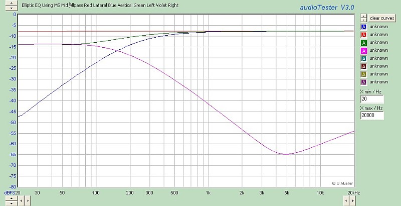
I wanted to provide an update which includes a rather interesting discovery.

Brickwall-limited material becomes "unlimited" when processed by the allpass filter of the EE...

Image
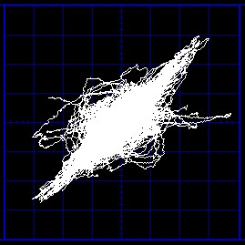
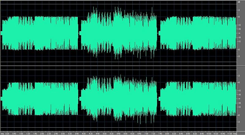
Daft Punk, "Harder Better Faster Stronger," No EE, Second Order, First Order.

The first envelope is with EE bypassed with brickwall limiting evident.
The second envelope is with 300 Hz second order EE. Note the 3-4 dB increase in peak level.
The third envelope is with 300 Hz first-order EE. There is a slight change in peak value but not much.

Statistics run on each of the segments confirm that the RMS levels are nearly identical but the middle example has peaks that are 4-5 dB hotter.

Material which has not been brickwall-limited does not "unlimit."

What appears to be going on is that in the second-order example L and R have undergone phase rotation from the original that "undoes" phase rotation in the brickwall limiter.

The effect of peak "unlimiting" due to cascaded phase rotation has been observed here: http://www.tonnesoftware.com/appnotes/a ... lpass.html
If the applied waveform is symmetrical top-to-bottom (i.e. has no even-order harmonic content) then the allpass can actually increase the signal's peak-to-peak amplitude.
It sure does...

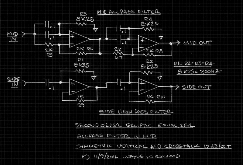
This is where it gets interesting. From Foti and Orban: http://www.orban.com/orban/support/orba ... th_1.3.pdf
A Typical Processing Chain—What Really Goes On When Your Recording is Broadcast

A typical chain consists of the following elements, in the order that they appear in the chain:

Phase rotator. The phase rotator is a chain of allpass filters (typically four poles, all at 200Hz) whose group delay is very non-constant as a function of frequency. Many voice waveforms (particularly male voices) exhibit as much as 6dB asymmetry. The phase rotator makes voice waveforms more symmetrical and can sometimes reduce the peak-to-average ratio of voice by 3-4dB. Because this processing is linear (it adds no new frequencies to the spectrum, so it doesn’t sound raspy or fuzzy) it’s the closest thing to a “free lunch” that one gets in the world of transmission processing.
What I think is happening is that some plugins use phase rotation as a first step in their brick-wall limiting.

When brick-walled material is broadcast that tightly-controlled envelope is immediately undone in the first process.

Instead of making the job of the AGC, Multi-band and Limiter easier brick-walling actually makes it harder.

This article discusses broadcast processing of clipped music which is not necessarily the same as "hyper-compressed phase rotated brick-walled" material.
Making Audio Better One Square Wave At A Time: https://www.telosalliance.com/images/Ma ... 20Time.pdf

What we have going on here is the second-order EE simulating the "undo" effects of broadcast phase rotation.
Overall the EE has 2 poles at 300 Hz; the Omnia or OptiMod 4 poles at 200 Hz.

Having brick-walled material undone in EE is not a desirable property.

Being able to identify phase-rotated brick-walled material and correcting it in mastering may be very useful: It can potentially identify artifacts that occur in broadcast.
"Unwrapping" phase rotated material and then processing dynamics conventionally might produce a more open, musical result.

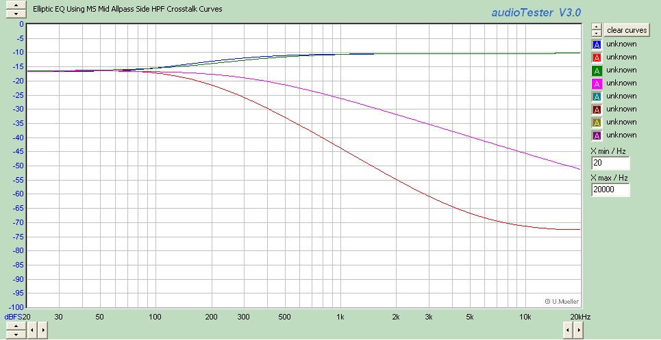
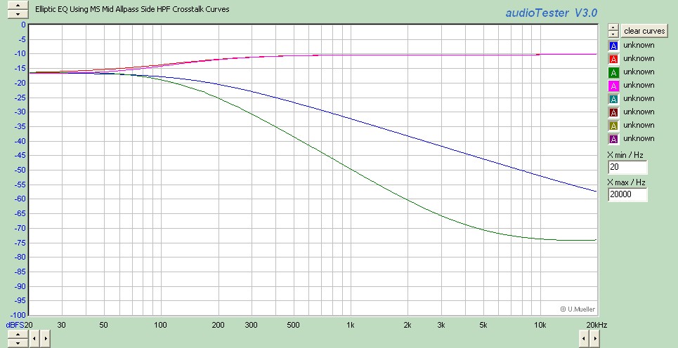
The overall Left and Right phase rotation produced by the the EE Side filter and the phase correcting Mid Allpass can be undone to prevent the undoing of brick-walled material.
It looks like an "inductive" allpass network, using a gyrator, could re-align Left and Right to "re-rotate" material back.
This would provide brickwall in/brickwall out.

Having a 4 pole 200 Hz allpass for Left and Right to "unlimit" also seems like a good tool to have...
User avatar
JR.
Posts: 3697
Joined: Sat May 24, 2008 7:21 pm
Contact:

Re: A Second Order Elliptic Equalizer for Vinyl Mastering

Post by JR. »

Before we leap to some conclusion about the merit of this, have you performed critical listening tests? It may not be hard to sound better than hard clipped audio, but does it sound un-clipped? If anything this suggests that you need more headroom to post process such data streams.

Note: I have been surprised before by signals that looked better, but sounded worse.

JR
Cancel the "cancel culture", do not support mob hatred.
Post Reply