side project - stereo that 1510, +-9v rails, p48, 10 way switches gain 12db-66db, mint tin size
3d render of better version not yet built
https://1580mixer.shutterfly.com/pictures/70
real
https://1580mixer.shutterfly.com/pictures/70#69
(pots were added later)
That1580 mini mixer
Re: That1580/1510 mini mixer
Onto version 2.0
https://1580mixer.shutterfly.com/pictures/103
changes from the initial prototype:
-implement wayne's excellent suggestions from post #11
current summing
his lcr pan scheme
-digital switching of pan,phantom, phase, gain control
-replace bluetooth/android interface with mini oled/5-way mini joystick
-reduce power rails to ~ +/6v
-mcu and summing section integrated onto backplane
-AT328p MCU @8Mhz 3.3v (shrinkified arduino pro mini = mcu+4 passives)
-have p/s and preamp cards properly removable with edge connector
-maybe 5v and or usb powered main supply since rails will be lower now
-fit it properly in tin this time, last go round it was slightly too large
-reduce to 5 channels in order to fit in screen/mini joystick/mcu controller on the backplane
-maybe some led level metering
I have the physical layout near where I want it. Without finding these samtec mini edge connectors I would not have been able to make these cards modular. Working with mini pitch headers was a nightmare on the last version.
There is some regret in lowering the channel count but there's no way to fit 6 channels in with these edge connectors and the mini oled screen. Also a little regret in ditching the android bluetooth interface, especially because it worked. But I'm leaning toward having everything in one box.
I checked the visibility/workability of this .66" screen and it's just about perfect. The contrast is high enough that it offsets the small characters. I'm planning on two screens: main screen for gain and pan --->>navigated to a secondary screen for phantom and phase. I can't fit everything into one screen of 64x48 characters.
The mcu runs at 3.3v, the oled runs as 3.3v, and THAT spi runs 3.3v. The screen actually wants 7v but it has an onboard charge pump that takes 3.3v and I suppose doubles it and 6.6v is close enough.
Will post schems soon. Have never done any digi controlled switches so I need to read up, and haven't figured out how or if to tie in all the device resets.

Re: That1580/1510 mini mixer
over the decades I have done my share of electronic switching, what do you have in mind?
JR
JR
Cancel the "cancel culture", do not support mob hatred.
Re: That1580/1510 mini mixer
JR I have not ignored you, just busy working on the power supply before I get into the switches. The previous version p/s used an ltm8049 micromodule (with bga footprint) for the opamp rails and the TI tps7axx low noise +-regulators. I did have room on the board to go this way, but decided to try to eliminate one daughter board as above and also get away from the bga footprint.
Decided to use +-5v rails as 15 was way overkill for line level. And settled on 5v-9v Vss. Using LT3032 dual ldo for the rails which clock in at 20/30uV noise, a little noisier than the TPS7a3/4 series regulators, but it's more compact and I doubt it's going to make any difference in the end.
I was looking over the LT8330 (which I use for phantom) datasheet and supposedly this can take care of my rails. Inductor selection is over my head but I used the coilcraft spreadhseet tool and cross referenced that with LT's eval board to choose LPD50x0 series. A few mm's smaller footprint of coilcraft vs. Wurth (too large) makes all the difference so I can just about fit in two lt8330 blocks for the rails now. I have no idea if switching noise will creep back into audio, so we'll see what happens when it's built.
It could be interesting to make some mini lt8330 generic dc converter boards. Maybe I can work out a way to jumper in all three topologies into one board - boost, sepic, and inverting. I'm trying to stay away from more daughter boards but this would sort of solve any p/s design in the future.
I looked briefly into led metering. The only place there is room is on the preamp daughter boards, and it looks like the easiest solution is for 1 mcu per daughter board to drive the led's. Not sure if I want to make things this complicated. Maybe there will only 1 stereo output meter, if anything. Or a tiny soc monitor speaker.
Also thinking about a dead man power switch that cuts off the Vdd supply to the mcu/oled section, just in case there is too much digital noise injected. Last go round this was not the case.
Re: That1580 mini mixer
I don't know how many audio paths you will have but I found huge utility from a bicolor LED per path, green for signal present and red for overload (say 3dB below saturation).
JR
JR
Cancel the "cancel culture", do not support mob hatred.
Re: That1580 mini mixer
JR I would like to have even simple metering as you suggested but there is not a lot of board space left. Adding 5 mcu's is a lot just to drive the led's. I'll keep thinking on it.
Meantime here is an attempt at digital switching for phantom, polarity and lcr pan.
Also attaching the backplane schematic which includes p/s, mcu, etc
Meantime here is an attempt at digital switching for phantom, polarity and lcr pan.
Also attaching the backplane schematic which includes p/s, mcu, etc
- Attachments
-
- 1580mixer.pdf
- (123.68 KiB) Downloaded 2282 times
-
- 1580card.pdf
- (57.56 KiB) Downloaded 2272 times
Re: That1580 mini mixer
No microprocessors required to make simple bi-color LED indications.
JR
JR
Cancel the "cancel culture", do not support mob hatred.
-
mediatechnology

- Posts: 5453
- Joined: Sat Aug 11, 2007 2:34 pm
- Location: Oak Cliff, Texas
- Contact:
Re: That1580 mini mixer
Nice work!
On the 1580 card why not put D1, the phantom On LED, in series with the node at R12/R13?
Sure there's some added forward drop but the current is free.
R35 wouldn't be required.
With high-current mics the LED might be too bright and a shunt/series R network could be used to divert some of the excess current.
It's sort of like in condensor mic designs where the various stages are series-stacked to harvest current.
If it were me I would also eliminate C12, C14 and C16 and let the delta network at C11, C13 and C15 do all the work.
In my experience R16 and R17 "de-Q" the effect of the input capacitor delta-network right at the device pins.
With C11, C13 and C15 installed there's no de-Q.
This goes completely against what we're told in the datasheet and is counter-intuitive but I found that with the 1570 it worked better with some resistance between the base and the C-network.
R16 and R17, already required for phantom protection, then serve as "base stoppers."
Re: That1580 mini mixer
c12,14.16 gone.
Metering will be done post unbalancing right before the 5k mixing resistors. Going with attiny84 somethings on each channel card, 10 leds, will try to emulate an lm3916 with the mcu. low current leds and peak metering should not be too much of a current draw. (led color render is messed up, it's supposed to show as 8 greens, 1 yellow, 1 red)
I'm hoping that those mini jacks (which are soldered to the motherboard) will squeak into the tins.
That's about it for the design I think. The rest is making it work and writing code.
- Attachments
-
- ADC.pdf
- (66.8 KiB) Downloaded 1197 times
-
- 1580card.pdf
- (106.38 KiB) Downloaded 1172 times
Last edited by weroflu on Sun Feb 27, 2022 9:58 am, edited 1 time in total.
Re: That1580 mini mixer
I did a lot of work with mcu based metering with one 4 channel meter still in use (I think?) in a professional product (APB 4 bus console). I just checked their website and it looks like they stopped making the big consoles but found this picture.
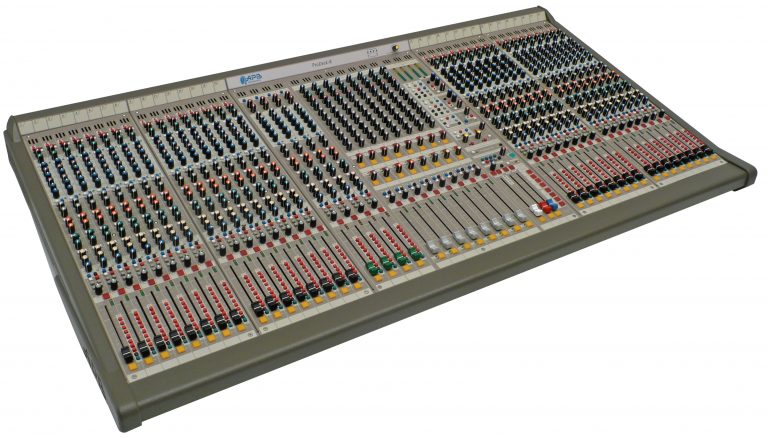
The meter in the master section used my simultaneous peak(dot)-VU(bar) display.
I learned a lot in the course of that design.
JR
PS: My suggestion for a simple two color (red for headroom, and green for signal present) display used only one op amps per channel.
The meter in the master section used my simultaneous peak(dot)-VU(bar) display.
I learned a lot in the course of that design.
JR
PS: My suggestion for a simple two color (red for headroom, and green for signal present) display used only one op amps per channel.
Cancel the "cancel culture", do not support mob hatred.