
Update May 13, 2021. The current schematics and tests results for "ULDO-Nacho," the Ultra Low Distortion Oscillator and Notch Filter, are posted here: viewtopic.php?f=6&t=887&p=16375#p16375
I decided to revisit the world of "Super Low Distortion Ultra Pure Audio Sine Wave Oscillators."
These oscillators are usually fixed frequency with sub-ppm THD levels and are often used to evaluate A/D or capacitor linearity.
The designs I looked at use either FETs, Silonex NSL32SR3 LED/Photocells or the SSM2018 for amplitude stabilization.
My goal is to see if a THAT2180 VCA can be used for amplitude stabilization.
The sub-PPM THD oscillators I found share a lot of common elements.
"Wien Bridge Oscillator With Low Harmonic Distortion," J.L. Hood, Wireless World, May, 1981: https://www.proaudiodesignforum.com/ima ... y_1981.pdf

"Wien Bridge Oscillator With Low Harmonic Distortion," Hood, Wireless World, May, 1981
J.L. Hood's 1981 Wien bridge oscillator using the National Semiconductor Silonex NSL395 LED/Photocell for amplitude stabilization.
PDFs of Wireless World articles mirrored in this post are courtesy of Kieth Snook: http://keith-snook.info
"Build A High Performance THD Analyzer," Bob Cordell, Audio, July, August, September 1981: viewtopic.php?f=12&t=805
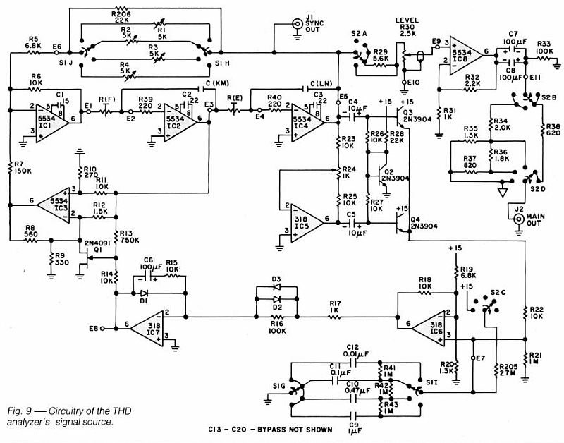
Oscillator Section of "Build A High Performance THD Analyzer," Bob Cordell, Audio, July, August, September 1981
Bob Cordell's tuneable design uses a state variable topology oscillator and FET amplitude stabilization.
The Cordell oscillator has an elegant yet simple rectifier section.
"Oscillator Keeps THD Below 1 ppm," Jeff Smith, EDN, November 11, 1994. https://www.proaudiodesignforum.com/ima ... 0_1994.pdf

"Oscillator Keeps THD Below 1 PPM," Smith, EDN November 10 1994.
The "Smith" oscillator uses an SSM2018 VCA which is no longer in production.
Cyril Bateman developed a sub-ppm oscillator for his "Capacitor Sounds" articles. The sub-ppm oscillator is here: https://proaudiodesignforum.com/images/ ... ound_1.pdf

Bateman 1 kHz Sub 1 PPM Test Oscillator
Bateman's oscillator, like Smith's, uses an SSM2018 VCA in an additive-type gain control.
Only a portion of the oscillator's feedback loop flows through the SSM2018.
The SSM2018's output adds a varying amount of signal to regulate level similar to "parallel" compression.
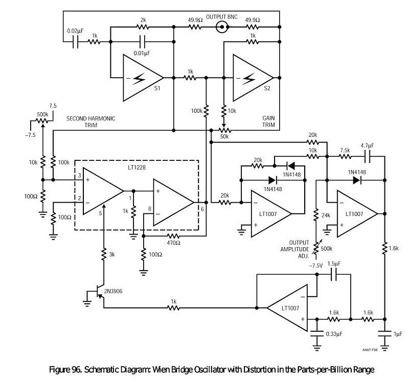
Jim Williams and Dale Eagar of Linear Technology published several articles on "ultra pure" and ultra pure oscillators using "super" composite op amps. See: viewtopic.php?f=6&t=421&p=4808
"Test 18-Bit ADCs with an Ultrapure Sine-wave Oscillator," Jim Williams, EDN, August 11, 2011.
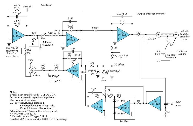
"An Ultra Pure Oscillator," Dale Eagar, Linear technology AN-67, 1996.
Williams' and Eagar's oscillators use a Silonex NSL32SR3 LED/Photocell for amplitude stabilization.
The NSL32SR3 is still in production and available from Allied Electronics, Digi-Key and others.
The fate of CdS photocell production is uncertain however.
Vicktors Mickevics developed a very good 1 and 10 kHz oscillator that he once sold on eBay. He posted the schematic on DIYAudio: http://www.diyaudio.com/forums/equipmen ... ost3116055
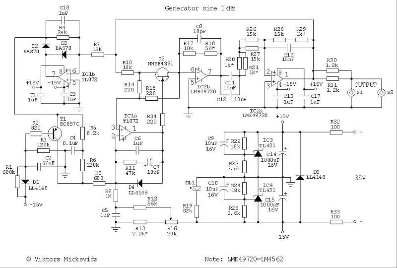
Mickevics Ultra Low Distortion Oscillator 1kHz
The Mickevics' oscillator uses an available JFET, the SMT MMBF4391, which is a 2N4391. The through-hole 2N4391 is still available from Mouser.
I built this oscillator and it performs very well.
R14/R15 linearize T2 as well as shunt the FET to reduce it's delta-R.
The use of IC1A to provide buffered linearity feedback to the gate is clever.
I'm not sure what T1 does - I think it appears to "kick-start" the loop on power-up.
The powering arrangement of this oscillator, using shunt regulators with no direct connection to supply ground, provides some advantages I'll cover later on.
The Janascard oscillator is very similar to the Williams and Mickevics oscillators using a Silonex NSL32SR3: http://www.janascard.cz/PDF/An%20ultra% ... 0%20dB.pdf

Janasek Ultra Low Distortion Oscillator
The Janasek oscillator uses the LME49710.
It's schematic is the most easy to follow.
If you look at the Janasek control loop you'll see that the NSL32SR3 is in parallel with an 18Ω resistor.
The delta-R of the NSL32SR3 is about 150-60Ω at an LED current ranging from 5-20 mA.
The net delta-R is only about 2Ω.
The gain change for stable operation is very, very small only about 0.005 dB.
The criteria for stable oscillation requires precise level control in all of these designs.
The Janasek, Mickevics or any of the previously cited oscillators can be easily modified to use a THAT2180 VCA using subtractive gain control.
The schematic of the oscillator without the control loop:
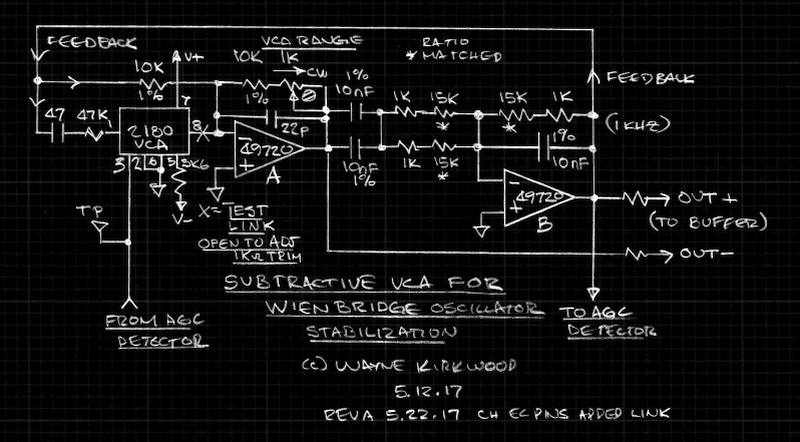
Subtractive VCA Stabilizes Ultra Pure Low Distortion Wien Bridge Oscillator
In order to optimize Janasek et al for use with a 2180 VCA a different approach was used to eliminate the 2180s I-V op amp and use the current output directly.
The Smith and Bateman Wien bridge oscillators use the SSM2018 to add a portion of the feedback signal to itself to vary gain.
The weighting of the VCA-controlled output is a fraction of the total feedback signal to reduce the amount of gain change versus the control voltage.
In Smith, the ratio is about 50:1; in Bateman about 3:1.
The SSM2018 is current-in/voltage-out and is non inverting.
The THAT2180 VCA core is current-in/current-out and inverts polarity.
(In traditional VCA applications the 2180's I-V op amp stage inverts polarity making the overall polarity non-inverting.)
By moving the 2180 so that it operates in parallel with the Wien stage inverter's input resistor we accomplish two things:
1) We take advantage of the 2180s current output and eliminate the I-V op amp and additional noise. At high gain reductions the 2180s noise is lower than the I-V stage resistor. Using the current output we eliminate a gain stage.
2) The inverting nature of the 2180 subtracts signal to control gain. Since we only need less than a dB of gain control (maybe 0.05dB?) the 2180 can operate in deep attenuation typically -50 to -30 dB. This reduces its noise and THD distortion considerably and allows larger amounts of control voltage to precisely control very small amounts of gain change.
Due to subtraction of signal the control slope is backwards.
As the attenuation of the VCA decreases (VCA gain increasing) the output level of op amp A decreases.
The 1 KΩ trim skews the gain of the Wien bridge inverter to set the amount of VCA attenuation when the loop has stabilized.
Typical attenuation can range from about -55 to -30 dB. I'm currently using -46 dB VCA attenuation.
As the 1 KΩ is varied, the THD and noise remains essentially constant leading me to believe the VCA is not significantly contributing to THD or noise.
Output from my version is taken from both op amp A and B to provide a balanced output and a possible phase inverter for the level detector similar to Smith's.
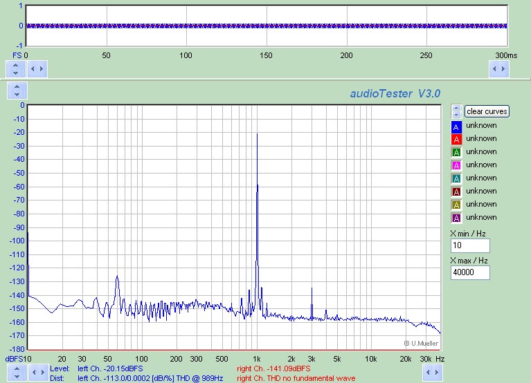
I built the Janasek oscillator using a THAT2180 VCA which allowed me to measure the distortion of the PCM4222.

PCM4222EVM 1 kHz THD Using the Janasek Ultra Low Distortion Oscillator Modified for a THAT2180 VCA
The combined oscillator and PCM4222EVM A/D THD is about 2 ppm.
The oscillator was built on an open unshielded Protoboard and hum is indeed present.
At 2 ppm - with quite a bit of the distortion likely the A/D - I'm within distance of sub-PPM performance.
Without building a notch filter its difficult to prove that the residual distortion - which is exceedingly small - is in the A/D.
What I have been able to determine is that the second and third harmonics drop into the noise floor just below -25 dBFS.
To prove that it wasn't necessarily the oscillator I first looked at the THD level of the oscillator's unbuffered output.
Regardless of how it was adjusted or configured the signature changes right around -25 dB FS.
I then added a variable gain output stage.
By increasing the oscillator's internal level and reducing the output level to compensate I was able to determine that the THD signature always changed at -25 dBFS regardless of what level the oscillator was running at internally.
At very high levels (>10V P-P) I could see some rise in the oscillator THD itself but at the 1-2V RMS range it falls into the noise floor.
This points to the A/D as being the dominate THD contributor:
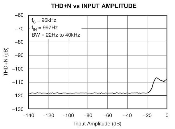
PCM4222 96 kHz THD vs Input Level
What I'm observing around -25 dBFS is consistent with how the PCM4222 is specified.
As Bruce Hofer has pointed out the possibility exists that both devices have higher distortion and the products cancel to make the measurement look better than it actually is.
See: Hofer, "Understanding Distortion Measurements" http://www.linear.com/docs/4134 (page 44)
In order to further prove the purity of the source I need a notch filter like the ones described by Smith and Janasek.
With the filter sets its possible to deeply null the fundamental, add gain so oscillator distortion rises above the converter noise floor and find the THD down in the mud.
From this measurement you can establish that the oscillator is (or is not) significantly better than the converter.
I'm confident that a THAT2180 VCA can be used to stabilize a sub-PPM THD audio oscillator.
The Control Loop
The control loop I used was similar to the Janasek with an additional op amp stage to provide the integration at the base of the LED driver transistor.
In Janasek he discusses the narrow lock range.
The VCA has a wide lock range.
Stabilization on power up is very quick and the amplitude does not drift.
The control loop is quite simple and the only improvement I think can be made is in the rectifier.
The rectifier is fairly non-critical but can be a source of harmonics.
The Smith, Bateman and Cordell rectifiers do not have op amps running open loop at zero cross and do not require reverse-polarity clamping.
The schematic of the control loop is here: viewtopic.php?f=6&t=887&start=13

