A Modern Loftech TS-1 Audio Test Set

Where we discuss new analog design ideas for Pro Audio and modern spins on vintage ones.
Post Reply
User avatar
mediatechnology
Posts: 5437
Joined: Sat Aug 11, 2007 2:34 pm
Location: Oak Cliff, Texas
Contact:

A Modern Loftech TS-1 Audio Test Set

Post by mediatechnology »

This thread is a copy of the Loftech TS-1 Schematic document thread. JR is in the process of considering a modern replacement for the ubiquitous Loftec TS-1 using modern DSP-based electronics.
JR. wrote: Fri Nov 03, 2017 11:39 am I could do that entire puppy today, even better using only a few digital chips... (somebody stop me...) :lol:

JR
Nobody stopped him. See: viewtopic.php?f=6&t=918&p=10757#p10764
Our current story picks up here: viewtopic.php?f=6&t=918&start=30#p10790

As a point of reference this is the original TS-1 schematic.

Loftech TS-1 Test Set Schematic

Image
Loftech TS-1 Schematic

Loftech TS-1 Schematic Large Format jpg: https://www.ka-electronics.com/images/j ... _Large.jpg (2MB)
Loftech TS-1 Schematic pdf: https://www.ka-electronics.com/images/p ... ch_TS1.pdf
User avatar
mediatechnology
Posts: 5437
Joined: Sat Aug 11, 2007 2:34 pm
Location: Oak Cliff, Texas
Contact:

Re: Loft TS-1 Schematics

Post by mediatechnology »

bump
pascal.verdet
Posts: 18
Joined: Tue Jan 25, 2011 5:38 am

Re: Loftech TS-1 Schematics

Post by pascal.verdet »

Studying this schema. I have simple question...
the MM74C926 is a 4-digit counter ... I understand how it works in frequency counter,
But, could you explain how do you relate the relative dB level, and its display ?
there is Q2,Q3 and Q4 act as saw tooth integrator ?

Thanks,
User avatar
JR.
Posts: 3697
Joined: Sat May 24, 2008 7:21 pm
Contact:

Re: Loftech TS-1 Schematics

Post by JR. »

pascal.verdet wrote: Thu Nov 02, 2017 9:12 am Studying this schema. I have simple question...
the MM74C926 is a 4-digit counter ... I understand how it works in frequency counter,
But, could you explain how do you relate the relative dB level, and its display ?
there is Q2,Q3 and Q4 act as saw tooth integrator ?

Thanks,
Q1, Q2, and Q4 serve as a pulse doubler to count every zero crossing so the frequency counter can update frequency every half second, instead of counting for a full second, so twice as fast and unrelated to the dB display.

The dB (log) conversions is performed by the 3046 transistor array where the signal varying Vbe has the fixed 0dB Vbe subtracted from it. This mV level voltage represents + and - dB relative to 0dB. The sawtooth generator is performed by the 3 sections of TL074 near the top center of the schematic. The +/- dB (log) voltage is applied to the + input while a resistor to ground from the - input causes the integration capacitor to ramp up or down with a rate of change representing how many dB. 0dB, or 0V would not ramp up or down. The integrator resets at a finite + or - voltage, so the count of completed ramps up or down per unit time represents how many dB. 8-)

I used a bifet op amps and polystyrene cap for the integrator. This count was more accurate than the front end. The overall dB accuracy suffered at high dB from the Rbb effective resistance in series with the logging transistor base-emitter (error was less than 1dB high at +20dBu but I could measure it). The dB accuracy at low level suffered from a couple different errors... first was noise floor of the front end, and second was gain bandwidth of the rectifiers. Accurately rectifying tiny levels at higher frequency becomes harder and harder since the rectifier has to slew from - one diode drop to + one diode drop in zero time. I was happy after much effort to realize a 20kHz -3dB point at -50dBu. With bandwidth dropping in half for every 10dB lower (i.e. 10kHz @ -60dBu).

An improved design could put a 2:1 compressor in front of this rectifier and realize a -100dB 20kHz bandwidth in theory, while in practice most VCAs have noise floors higher than -100 dbu.

There are lots of subtle circuit tricks all around that design, unusual for one product to have so much novel circuitry in it. I hope this explains how that dB conversion block works, while there could be a whole chapter written about the other blocks too.

JR
Cancel the "cancel culture", do not support mob hatred.
pascal.verdet
Posts: 18
Joined: Tue Jan 25, 2011 5:38 am

Re: Loftech TS-1 Schematics

Post by pascal.verdet »

Many thanks JR.
Since dB and frequency are common input J1,
Is this the same path for the two functions, or is the difference in operation just made by the S2 switch ?
Pin 12 of 74C926 are the clock input. What is the secret to differentiate the audio level, and the frequencies?
What is the exact role of the three op amps (U1 10,9,8 U1 3,2,1 U2 3,2,1 )in upper middle schema, it's just for auto scale, or anything else

Pascal
User avatar
JR.
Posts: 3697
Joined: Sat May 24, 2008 7:21 pm
Contact:

Re: Loftech TS-1 Schematics

Post by JR. »

pascal.verdet wrote: Fri Nov 03, 2017 6:54 am Many thanks JR.
Since dB and frequency are common input J1,
Is this the same path for the two functions, or is the difference in operation just made by the S2 switch ?
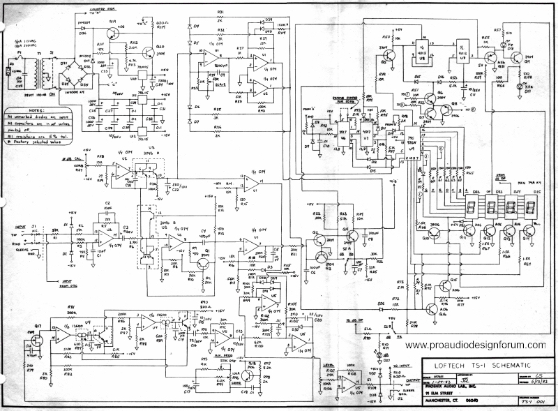
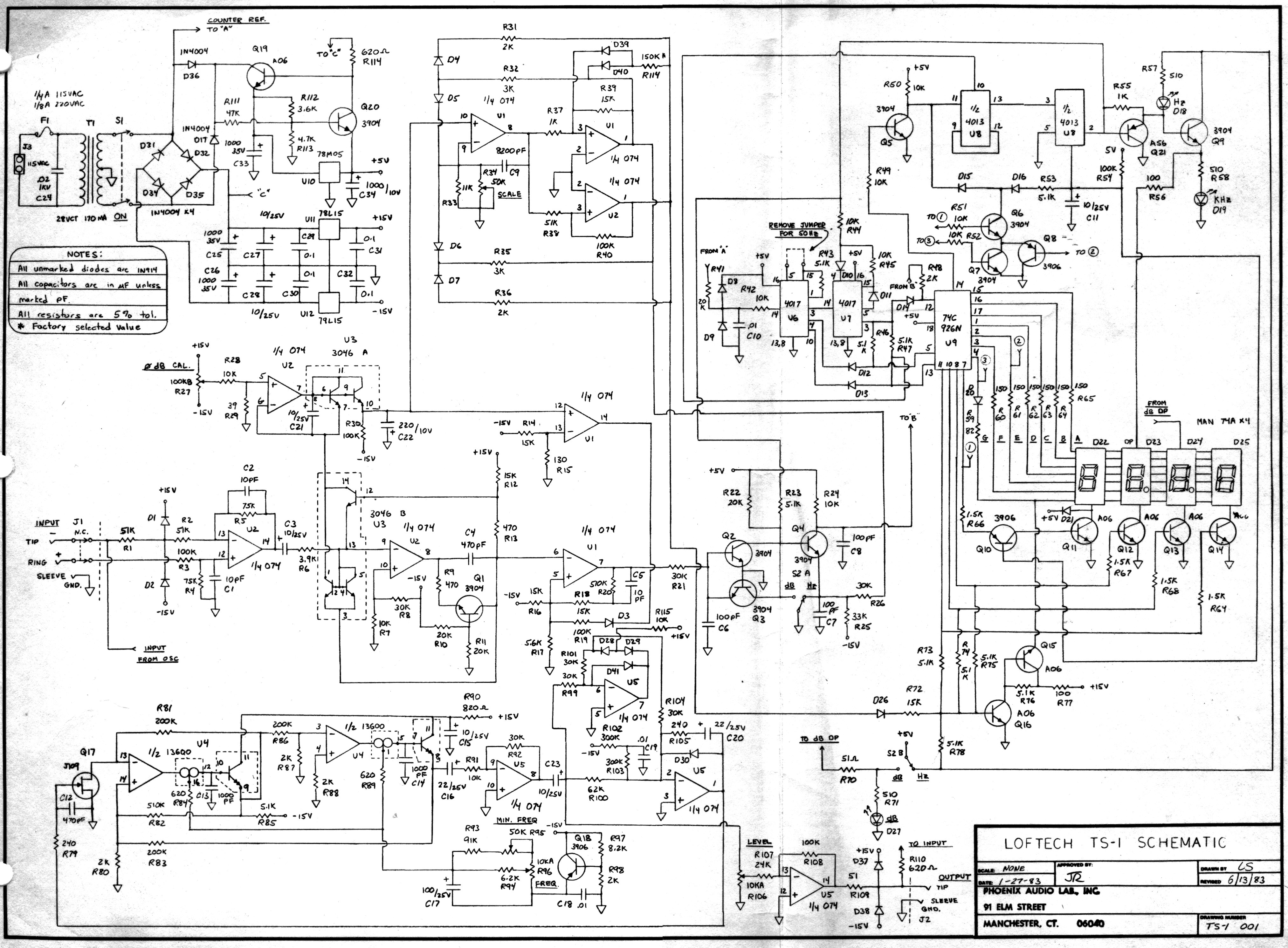
There is only one input audio path...

The frequency counter grabs the audio from the output of the rectifier op amp that is naturally amplified by the rectification process. A comparator formed by one section of op amp is gated off at low amplitude so the frequency counter does not try to count noise. As I mentioned yesterday the transistors q2,q3,q4 serve as a pulse doubler so every zero crossing is counted and 1/2 second period can impute cycles per second.

Pin 12 of 74C926 are the clock input.
the 4017 cmos dividers generate a time base by dividing down the mains frequency. Probably gated at 1/2 second rate.

First divider divides by 5 or by 6, second divider is toggled on/off to scale between Hz and kHz
What is the secret to differentiate the audio level, and the frequencies?
Secret?
What is the exact role of the three op amps (U1 10,9,8 U1 3,2,1 U2 3,2,1 )in upper middle schema, it's just for auto scale, or anything else

Pascal
Those 3 op amps are the function I described yesterday (sawtooth generator for dB counter.) The mV level log of the audio dB goes into pin 10 + input. The R to ground from - input pin 9 creates a linear current draw that charges capacitor C9 up or down for + or - dB voltage input.

The two op amps U1 and U2 pins 1,2,3 serve as comparators to quickly reset the ramp at positive or negative ramp voltage limits so it will continue to ramp. The count of number of completed ramps up or down in the 1/2 second time window represents how many dB above or below 0dB is present. 0dB present 0V to the integrator, for zero current, and zero ramps up/down in the unit time.

Since i designed this almost 35 years ago, some details are a little fuzzy,,, there was a single switch to toggle between frequency counter and dB meter, all the other stuff (like frequency counter auto ranging) was automatic.

In hindsight putting a frequency counter on the output of a sine wave generator that covered from <20 Hz to >20kHz with one knob was inviting a lot of disappointed customers trying to dial in exactly 1,000 Hz and getting a couple Hz one side or the other. :roll:

JR

PS: I still ponder how much easier it would be to make one of these using a modern (cheap) microprocessor... I have to keep telling myself don't even think about it. :lol:
Cancel the "cancel culture", do not support mob hatred.
User avatar
mediatechnology
Posts: 5437
Joined: Sat Aug 11, 2007 2:34 pm
Location: Oak Cliff, Texas
Contact:

Re: Loftech TS-1 Schematics

Post by mediatechnology »

In hindsight putting a frequency counter on the output of a sine wave generator that covered from <20 Hz to >20kHz with one knob was inviting a lot of disappointed customers trying to dial in exactly 1,000 Hz and getting a couple Hz one side or the other.
I saw a lot of TS-1's in the field that had multi-turn pots installed for that reason.

Just about every tech shop I visited in my travels had a TS-1.
It's definitely a classic.
I wonder how many have been made.
User avatar
JR.
Posts: 3697
Joined: Sat May 24, 2008 7:21 pm
Contact:

Re: Loftech TS-1 Schematics

Post by JR. »

mediatechnology wrote: Fri Nov 03, 2017 10:51 am
In hindsight putting a frequency counter on the output of a sine wave generator that covered from <20 Hz to >20kHz with one knob was inviting a lot of disappointed customers trying to dial in exactly 1,000 Hz and getting a couple Hz one side or the other.
I saw a lot of TS-1's in the field that had multi-turn pots installed for that reason.
A later version after Gold Line took it over added a fine frequency trim pot...

Just about every tech shop I visited in my travels had a TS-1.
It's definitely a classic.
I wonder how many have been made.
For years the owner of Gold Line (Marty?) would brag to me at trade shows about how many he shipped, until he realized how much it irritated me. In fact I probably had to tell him. IIRC when I mentioned royalty he puckered up and changed the subject. :lol:

Knowing that would just depress me... I get nada... not even a taste on the companion book I co-authored. I also find remarkable how much Gold Line raised the price.... :roll:

I could do that entire puppy today, even better using only a few digital chips... (somebody stop me...) :lol:

JR
Cancel the "cancel culture", do not support mob hatred.
pascal.verdet
Posts: 18
Joined: Tue Jan 25, 2011 5:38 am

Re: Loftech TS-1 Schematics

Post by pascal.verdet »

Hi JR, and Wayne,
Many thanks for your help.
I'm studying the TS-1, because I would like to make the same, with low distortion oscillator,
frequency counter, and dB meter, based on THAT DN119 "Wide Ranging dB Meter" with a PIC micro controller for the both frequency counter
dB meter and display, and I will try to use the Elliott Sound Products method for oscillator.
http://sound.whsites.net/project86.htm
Pascal
User avatar
JR.
Posts: 3697
Joined: Sat May 24, 2008 7:21 pm
Contact:

Re: Loftech TS-1 Schematics

Post by JR. »

Maybe I will have to tell you exactly how to do this since I have only been thinking about this for more than 3 decades.

Hint, it won't involve much from the original design.

JR

PS: The sine wave generator in the TS-1 is pretty remarkable for what it is... IIRC around 0.15% THD and fast settling time, not to mention pretty stable for a voltage controlled (current controlled SVF oscillator) over time and temp. I could have made is lower distortion (how low do you want?) but in my judgement customers wouldn't be willing to wait for a low distortion agc loop to settle.

Don't worry my next gen solution has zero settling time. :lol:
Cancel the "cancel culture", do not support mob hatred.
Post Reply