A Modern Loftech TS-1 Audio Test Set
Re: A Modern Loftech TS-1 Audio Test Set
Any progress to report on this John??

Re: A Modern Loftech TS-1 Audio Test Set
I have been distracted by life,,, always things to fix and/or improve.
I have wanted to do a next, better version of this for almost 30 years, and the modern technology would make this easy-peasy. That said I don't need yet another time/money black hole. I determined decades ago this would not be a hugely profitable venture.
I like the idea of a drop in board swap to bring an old tired TS-1 back to life, stronger and better, but it is hard to avoid feature creep as this thread reveals. A digital/software based audio engine could support lots of new tricks, but display/control interface needs to accommodate the new tricks.
The simplest is just a board swap that covers the original functions (only better).
I would still love to do something like this, but maybe not this lifetime...
JR
Cancel the "cancel culture", do not support mob hatred.
-
mediatechnology

- Posts: 5466
- Joined: Sat Aug 11, 2007 2:34 pm
- Location: Oak Cliff, Texas
- Contact:
Re: A Modern Loftech TS-1 Audio Test Set
Fluke 8050A Meter Displays: https://madnessinthedarkness.transsys.c ... r_displaysI like the idea of a drop in board swap to bring an old tired TS-1 back to life, stronger and better, but it is hard to avoid feature creep as this thread reveals. A digital/software based audio engine could support lots of new tricks, but display/control interface needs to accommodate the new tricks.
The simplest is just a board swap that covers the original functions (only better).

-
mediatechnology
- Posts: 5466
- Joined: Sat Aug 11, 2007 2:34 pm
- Location: Oak Cliff, Texas
- Contact:
Re: A Modern Loftech TS-1 Audio Test Set
WRT output squarewaves:
The DAC output will require a buffer to drive balanced audio loads.
Make the output buffer switch from linear operation to squaring with a simple switch or transmission gate controlled by a port pin.
Switch an internal circuit node in the buffer to increase an internal stage gain or mode change from op amp to comparator.
There. Done. DAC ringing avoided.
Re: A Modern Loftech TS-1 Audio Test Set
It seems we've discussed this before but are you worried about "Gibbs" Phenomenon? This strikes me as more of a cosmetic issue, and the waveform should be square enough for typical (tilt) testing. The amount of deviation from a perfect square wave is reduced as the HF bandwidth of the DAC output is increased.mediatechnology wrote: ↑Tue Feb 19, 2019 6:43 am WRT output squarewaves:
The DAC output will require a buffer to drive balanced audio loads.
Make the output buffer switch from linear operation to squaring with a simple switch or transmission gate controlled by a port pin.
Switch an internal circuit node in the buffer to increase an internal stage gain or mode change from op amp to comparator.
There. Done. DAC ringing avoided.
Of course the features for an imaginary version will only be limited by imagination. I imagine a linear stage saturated to output a square wave could have perturbations as it comes out of saturation and reverses direction twice per cycle, could even worse than Gibb's squiggles.
JR
Cancel the "cancel culture", do not support mob hatred.
-
mediatechnology
- Posts: 5466
- Joined: Sat Aug 11, 2007 2:34 pm
- Location: Oak Cliff, Texas
- Contact:
Re: A Modern Loftech TS-1 Audio Test Set
You mean like the 74C926?in large scale production I have seen small specialty circuits come and go
I have an idea: Why don't you code a PIC to emulate the 74C926 so that TS-1 owners who need one aren't orphaned.
TS-1 Schematics: viewtopic.php?f=16&t=404&p=4531
Provide us the source code and pinout translation and someone else, if you don't want to, can DIY the adapter.
Most of the 74C926 available on ebay are from China and may not be real.
Domestic ones run $20-45 each and apparently a lot were used in process control displays.
(For that matter you could use a PIC to replace the entire upper-right-hand portion of the schematic and re-issue an updated TS-1. LM13700s are still being made by TI and IIRC Uli.)
All hat, no cattle.
I want to see some cattle.
A PIC 74C926 replacement is a start.
And I can assure you that if you come up with something I won't piss all over it.
BTW I have no clue about the Gibbs thing. I would also buy one of these Fluke things in a heartbeat: viewtopic.php?f=6&t=918&p=12730#p11246
Re: A Modern Loftech TS-1 Audio Test Set
As I recently discovered the hard way, after having to figure out what I did 40 years ago.mediatechnology wrote: ↑Thu Mar 17, 2011 2:47 pm This thread is a copy of the Loftech TS-1 Schematic document thread. JR is in the process of considering a modern replacement for the ubiquitous Loftec TS-1 using modern DSP-based electronics.
Nobody stopped him. See: http://www.proaudiodesignforum.com/foru ... 757#p10764
Our current story picks up here: http://www.proaudiodesignforum.com/foru ... =30#p10790
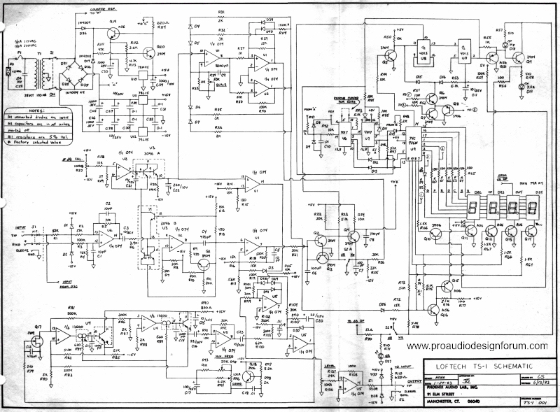
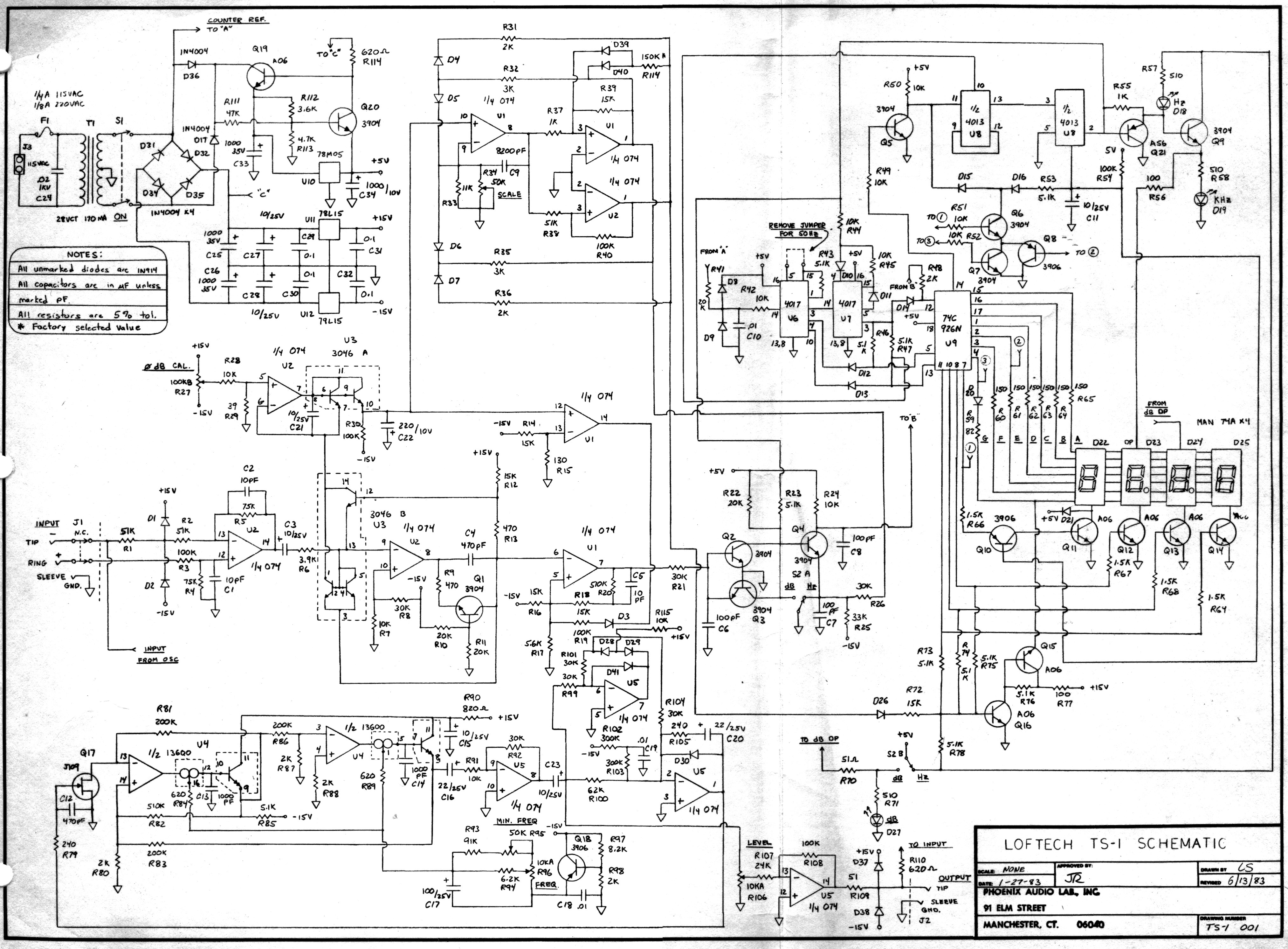
As a point of reference this is the original TS-1 schematic.
Loftech TS-1 Test Set Schematic
Loftech TS-1 Schematic
Loftech TS-1 Schematic Large Format jpg: https://www.ka-electronics.com/images/j ... _Large.jpg (2MB)
Loftech TS-1 Schematic pdf: https://www.ka-electronics.com/images/p ... ch_TS1.pdf
note #1: the top of the frequency control pot is connected to ground 0V
note #2: the bottom of the frequency pot is connected to approximately -2V (emitter of pnp buffer) shown connected in schematic but not labelled for voltage.
note #3: The -V pin of 13600 (pin 6) is connected to the -2V supply
note #4: the +V pin of 13600 (pin 11) is connected to +5V, not +15 like schematic.
The PS rails voltages of the OTA was reduced to improve thermal frequency stability, with full +/-15v rails the frequency would drift as it heated up or cooled down at frequency extremes.
The current mirror input to the OTA is roughly 2 diode drops above the 13600 -V when getting serious current, so the frequency pot is pretty much out of the picture at the LF end, the LF start up current is supplied by 50k PCB trimmer. Without this it was difficult to insure reliable LF start up... This trim was factory set for 10Hz IIRC.
Just this last week two people contacted me about helping them repair their TS-1.
JR
Cancel the "cancel culture", do not support mob hatred.