
Gold wrote: ↑Thu Feb 01, 2018 11:51 amThis looks great Wayne. It's much more product like. Could you expand on the gain switching of the 1240's? I don't think I've seen that before.mediatechnology wrote: ↑Wed Jan 31, 2018 3:38 pm By switching the THAT1240 in a unique way its gain can be varied from -6, to 0 and to +6 dB. This eliminates the requirement for additional gain or attenuation stages that would add a differential phase delay to one process path but not the other. High frequency crosstalk performance is maintained.

The -6dB summation was a real "doh!" Homer Simpson moment. So obvious.
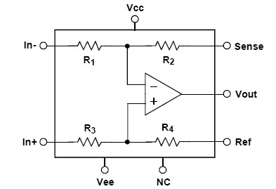
The identical value input resistors, internal to the 1240, form a 1/2 voltage divider for the non-inverting input and reference input when driven by 0Ω sources.
By connecting the inverting input and sense input of the 1240 back to the output to make it a follower, the 1/2 attenuation of the passive divider is preserved.
On the current MS Matrix pin 2 is grounded and the mono sum for identical inputs is +6dB.
The bias resistors that are shown in three of the configurations are required if the input floats.
(The bias current is typically around 900 nA IIRC.)
If they're connected to op amp outputs the resistors are somewhat redundant.
I put them in to aid troubleshooting in case the driving stage is removed from its socket.
When a relay is switching the input bias resistors are required.
