mediatechnology wrote: ↑Tue May 01, 2018 5:37 pm
I'm going to have to look at those moving parts again.
Glad I don' have to solder yours up on some perfboard.
Yup, building a console that way would be rough, but I know one guy who did one... I was never that crazy.
I've made numerous simple meters with LM339, oddly I never made a meter using LM391x series.... I did prototype a simultaneous peak/ave meter with a 3916(?) by multiplexing between peak (dot) and ave (bar), but never used any in production.
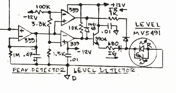
The first LM339 is a negative peak detector using the open-collector output of the LM339.
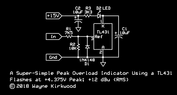
I still think the 8 part one with the TL431 is pretty simple and slick. (7 discounting bypass.)
I think I'm ready to take on the challenge of an "all TL431" bi-color two threshold.
sounds like good clean fun.
I might be able to do it with 3X TL431 by borrowing some of JRs moving parts in his bi-color flasher.
The low-level threshold might require a third TL431 for bias.
Am I limited to a two or three pin LED?
In my kit business I used 3 pin bicolor LEDs. I made a slick level threshold circuit (used inside my CX decoder kit to calibrate playback level) from a PNP LTP with the two collectors driving the two different colors... green for below threshold, red for above, and both colors lit for just right. Make one of those with less parts.

At Peavey they had a two pin bicolor LED in the system so I used that. In my current drum tuner the SMD bicolor has 4 pads so each LED can be addressed independently.
I probably don't even remember what every single component does in my old console circuit, but my signal present/OL indicator was tweaked for presentation to give an easy to interpret, pleasing display, "and" not corrupt the audio channel grounds, or PS with current spikes. As I recall it took more than one attempt to get it right. I wasted a bunch of time trying to make a useful display from the third color (both), but it never seemed distinct enough or obvious enough to use. The either/or green or red only seemed less subject to misinterpretation. The only thing (main thing) I didn't like about that circuit was the nonlinear loading from the multiple sampling diodes. I only sampled audio from low Z op amp outputs, but ideally every load in a high performance signal path should be linear.
I recall one later (smaller) console I did with tons of alternate inputs but only a modest meter bridge. Bi-color signal present/OL circuits on every internal audio path was extremely useful for A) finding signals, and B) keeping them clean. At least one popular mixer sold back then was notorious for not sampling clipping in the input channel pre-fader, while spending millions advertising that they had high headroom (cough). I could easily demonstrate hard clipping with their mixer without triggering any OL indication

but the sheeple believed the advertising and figured they were clipping some later path with less headroom.

Another obscure trick I did inside a monitor console was a variant on my FLS invention using a compound differential pair with multiple input transistor so only the one loudest, highest voltage device, steals all the current. I bused all the inputs together into this compound differential so you could scan across and see which one channel was the loudest by a line of LEDs across the top of the strips, as that one (loudest) input would typically be the channel with a mic feeding back.
JR
PS: Another different OL indicator was used in my final kit tape NR (one with all the side chain tricks
http://www.johnhroberts.com/p-522.jpg). I was using a complex op amp ripple filter in the side chain with the inverting op amp held at ground for nominal signal level, but losing negative feedback when the op amp output saturated causing the - input to rise. This - input fed the base of transistor to light an OL LED when that op amp saturated. Looks like I used two transistors per to provide some overload hold time and invert polarity to accommodate my common cathode bi-color LED.
Cancel the "cancel culture", do not support mob hatred.


