Now that I have Win 7 and the Focusrite installed on the test bench computer I made some measurements using my new tool.
Gain Measurements
I installed two 4K99 in series with the input and installed J1 (10Ω termination) to create a 60 dB pad.
I then input 0 dBu into the pad and read the out put level.
All linked except the ones listed...
J4 Open; Output = -54 dBu (Pad reality check: Front end unity gain, +6 in the double-balanced output)
J5 Open; Output = -20 dBu (VR set for +40 dB gain)
J6 Open; Output = -8.3 dBu
J7 Open ; Output = -4.2 dBu
J4-J7 linked; Output = +1.6 dBu
J6 and J7 Open; Output = -10.6 dBu
Frequency Response Measurement
Frequency response with the servo switched on and off.
With the servo off the preamp has response to DC.
The green trace is limited by the response of the Focusrite 2i2.
With the servo on there is a derived 12 Hz high pass response.
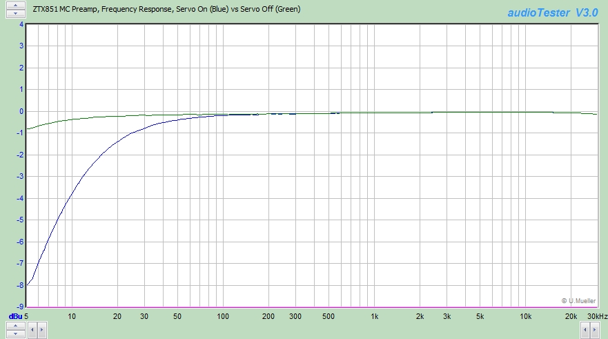
ZTX851 MC Preamp Frequency Response Servo On Blue vs Servo Off Green
Flat Balanced Input Moving Coil Phono Preamp Construction Information
- mediatechnology
- Posts: 5456
- Joined: Sat Aug 11, 2007 2:34 pm
- Location: Oak Cliff, Texas
- Contact:
- mediatechnology
- Posts: 5456
- Joined: Sat Aug 11, 2007 2:34 pm
- Location: Oak Cliff, Texas
- Contact:
Flat Balanced Input Moving Coil Phono Preamp Twin Tone IM Measurements
Twin Tone Distortion Measurements
I made some twin tone (19/20 kHz 1:1) distortion measurements.
The Focusrite 2i2's L/R outputs were passively mixed in the input attenuator used to drive the MC preamp board.
The two outputs were injected into the input attenuator at 0 dBu each: Both were attenuated by -60 dB.
The MC preamp gain is +62 dB.
Since the sum of the two tones were to hot for the converter I reduced the input level slightly. The dBu scale is relative.
ZTX851 Moving Coil Preamp Twin Tone_Distortion Gain 62 dB
The only visible IM is f2-f1 at 1 kHz.
Relative to the carrier level the f2-f1 is -90.2 dBc, 0.0031%, or 31 ppm.
(The spurs that are seen from 800 Hz to 10 kHz at -105 dB are a DAC artifact.)
I couldn't sum the DAC outputs the same way to perform a loop-back test of the converter but did use another method - not particularly graceful - to confirm that the f2-f1 spur is in the DUT.
Re: Flat Balanced Input Moving Coil Phono Preamp Construction Information
ding ding ding, we have a winnah... two-tone IMD at 19:20kHz is my favorite test for characterizing phono preamps. If you factor in the RIAA EQ the 1kHz distortion product will get 20dB more boost than the 19/20kHz. This makes -60dB nonlinearity more like -40dB. Typical THD gets rolled off by the RIAA curve.
Back in the 70s-80s when I was still actively tweaking phono preamps I modified my heathkit SMPTE IMD analyzer to be more difficult, since by the 70s, 7kHz was already too easy. 19:20kHz was a fair test and all inband, as compared to the alphabet soup of exotic proposed new tests.
To add even more gain to the RIAA eq boost effect maybe move the two test tones even closer together. 50Hz spacing, and distortion spur would get almost another 20dB boost relative to 20kHz.
Have fun...
JR
PS: Sorry for repeating my old stories (yet again), but it seemed almost on topic.
Cancel the "cancel culture", do not support mob hatred.
- mediatechnology
- Posts: 5456
- Joined: Sat Aug 11, 2007 2:34 pm
- Location: Oak Cliff, Texas
- Contact:
Re: Flat Balanced Input Moving Coil Phono Preamp Construction Information
Thanks John!
I'm still learning the "sweet spot" of the Focusrite 2i2 and decided that it would be better to control my DAC output level with the analog Monitor control rather than set the output level to -15 dBFS to run my tests.
Using a digital output level of -1.5 dBFS and lowering the Monitor level I got better results that are not contaminated with DAC noise.
This is the noise floor without twin-tone stimulus.
The DAC output is live but no tone is being generated.
Note the spurs around 1 kHz not related to stimulus.
ZTX851 MC Preamp Twin Tone Distortion Gain 62 dB No Signal
The following image is with 19/20 kHz 1:1 with the output level of the DUT set to 0 dBu measured by a wide-band true RMS Fluke 8050.
The input level is 645 µV RMS; Gain is +61.6 dB.
The input level of the 2i2 was reset to match the calibration of the Fluke meter.
Because f1 and f2 sum, they are about 3 dB lower than the carrier level used to compute distortion.
The sidebands skirting around f1 and f2 are likely internal to the DAC since it is now running 14 dB hotter.
ZTX851 MC Preamp Twin Tone Distortion Gain 62 dB
f2-f1 is now at -94.7 dBc, 0.0018% or 18 ppm.
Re: Flat Balanced Input Moving Coil Phono Preamp Construction Information
I was pleasantly surprised when I made my DIY two-tone IMD that the THD of the 10k and 20k sine waves was not that critical. The heathkit analyzer just performed a simple LPF on the product output so any THD on the two HF tones was scraped off too.
JR
JR
Cancel the "cancel culture", do not support mob hatred.
- mediatechnology
- Posts: 5456
- Joined: Sat Aug 11, 2007 2:34 pm
- Location: Oak Cliff, Texas
- Contact:
Re: Flat Balanced Input Moving Coil Phono Preamp Construction Information
I hadn't thought about the post-EQ magnification of the lower-order products because I'm often slow to catch on to your past comments.
Twin tone seemed to be about the only way I could meaningfully quantify distortion of the DUT but now that you mention it it is a very revealing test in an RIAA EQ'd chain.
Your comments WRT passive input pole servos has stuck with me.
In the very brutal world of RAW playback the servo takes a high frequency beating.
Once the servo op amp stops being an op amp and its output distorts its feeding that distortion back into the signal path.
A passive input pole reduces servo op amp bandwidth requirements and lowers HF distortion.
Re: Flat Balanced Input Moving Coil Phono Preamp Construction Information
Exactly, I killed a lot of brain cells soaking RIAA stages in beer.mediatechnology wrote: ↑Sat Dec 14, 2019 12:01 pm I hadn't thought about the post-EQ magnification of the lower-order products because I'm often slow to catch on to your past comments.
Twin tone seemed to be about the only way I could meaningfully quantify distortion of the DUT but now that you mention it it is a very revealing test in an RIAA EQ'd chain.
I learned my lesson about op amp GBW limitations designing active anti-image filters connected to the output of BBD delay devices back in the 70s, with tons of HF clock energy to attenuate. This was made worse by the typical GP op amps available back then with limited slew rate/GBW. I figured out that a real pole, placed before the active filter stage made the op amps (even those old op amps) much better behaved.Your comments WRT passive input pole servos has stuck with me.
In the very brutal world of RAW playback the servo takes a high frequency beating.
Once the servo op amp stops being an op amp and its output distorts its feeding that distortion back into the signal path.
A passive input pole reduces servo op amp bandwidth requirements and lowers HF distortion.
Servos can be another example of asking op amps to operate outside their comfort zone. In fact I like the idea of passive LPF before any active stage exposed to the outside world. Not to mention that RF can sneak back into output lines too. Note: some servo input signals are already LPF before they reach the servo but still good practice.
Thanks for the kind words.
JR
Cancel the "cancel culture", do not support mob hatred.
Re: Flat Balanced Input Moving Coil Phono Preamp Construction Information
It would appear there is no demand for M7 Al acorn nuts in UK M6 and M8 are available in a variety of gaudy colours for people who like that sort of thing. I'll take a risk on the M6 and drill out the thread. Cheap enough if I get it wrong...
Re: Flat Balanced Input Moving Coil Phono Preamp Construction Information
I drilled out 1/4-20 nuts, also because I couldn't easily get M7 acorn nuts. I was hesitant, but in the end it wasn't a problem at all, worked like a charm.
Re: Flat Balanced Input Moving Coil Phono Preamp Construction Information
I have finally "boxed" my incarnation of the Moving Coil Phono Preamp. The Mean Well power supply will probably get replaced and relegated to prototype use. It is a surprisingly good supply, but I still need to measure its performance in the box. The turntable connection uses CAT 6A cable. The amp compartment is magnetically shielded.
Now it needs to move into a permanent setup.