Mid Side M-S Matrix Construction Information
Posted: Fri May 08, 2009 9:51 pm
This is a clone of the post in the original thread. We might want to put build questions in this thread.
MS Mid Side Encoder/Decoder PC Boards: https://ka-electronics.com/shop/index.p ... imple%20MS
Update 5/12/2015:
PDF Assembly Instructions are here: https://www.ka-electronics.com/images/p ... ctions.pdf
Added Mouser Project Manager bill of materials for the Precision MS Matrix.
These lists are not editable but you can "order" the project to move it to your shopping cart, then save the cart as a project to allow editing.
There are two lists one with, and one without, THAT ICs.
I chose an LME49860 for the 5532 location.
There are no bridge rectfiers on the BOM for phantom protection: Most people don't use them.
Without THAT ICs https://www.mouser.com/ProjectManager/P ... 96947b82d5 (material cost as of 9/2/2013 in USD $37.68)
With THAT ICs https://www.mouser.com/ProjectManager/P ... 246710b37f (material cost as of 9/2/2013 in USD $81.88)
Here's a preliminary bill of materials:
13) 8 pin sockets
4) THAT1246 IC1, IC2, IC7, IC8
4) THAT1240 IC3, IC4, IC10, IC11
1) NE5532 IC9
4) THAT1646 IC5, IC6, IC12, IC13
9) 3 pin Phoenix terminal blocks Mouser 651-1725669 (Or 10 if you want a ground tie block)
14) 0.1/100V Mono Ceramic Mouser 581-SR201C104KAR (There are spots for a lot more but 14 are enough)
I stuffed C2, C3, C13-16, C18, C19, C24, C25, C32-35
2) 1R 1/4W R1 and R2(Flameproof/fusible is better but generic carbon film if that's all that's available)
2) 1N4004 D1, D2
8) 10uf radial NP or polarized 25V or greater C38-41, C42-45
2) 47uF/35V C36, C37
2) 22pF/100V Mouser 581-SR151A220JAATR1, C46, C47
2) 10K 1% Mouser 271-10K-RC, R3, R6
2) 20K 1% Mouser 271-20K-RC, R4, R5
4) DB-104 Bridge (optional for phantom power protection) BR1-4
8) 0.1" 2 Pin headers with jumper clips (To bypass various inserts at BR, BL, CS, CM, FS, FM, GR, GL)
Power Supply requirements:
+/-15V to +/-18V at ~ 40 mA. I recommend 18V rails as it buys you slightly more headroom in the Encoder Mid channel.
This is a stuffing guide:
Large format file: http://www.ka-electronics.com/Images/gi ... _large.GIF
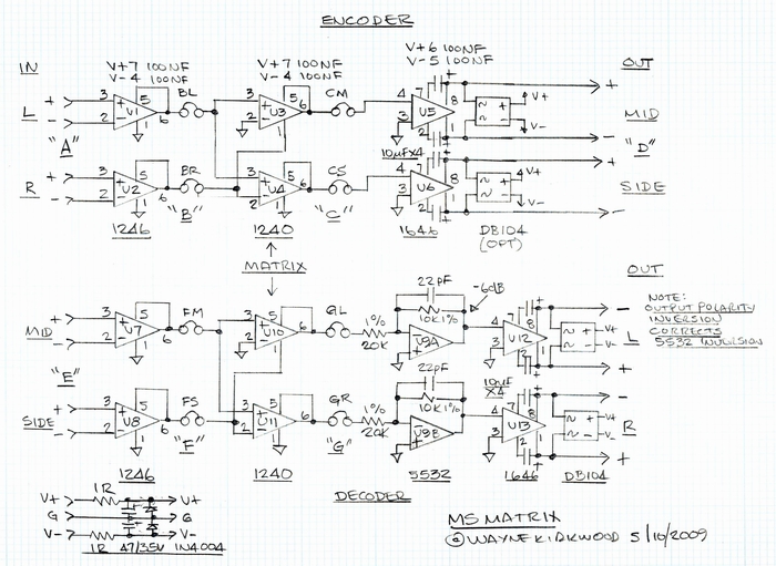
The flow diagram. Note that points B, C, F and G correspond to the header connections.

Note that the Encoder and Decoder are interchangeable. For highest accuracy I recommend that the left side be used as the Encoder and the silkscreen is marked that way. For -6dB encoding, the decoder side can be used but it's far less accurate since the 1% MF resistors of the -6dB stage are in the Mid/Side Domain where they affect crosstalk. When the -6dB stage is used in the decoder, the accuracy of the resistors are far less critical since the only affect channel balance by a very small amount.
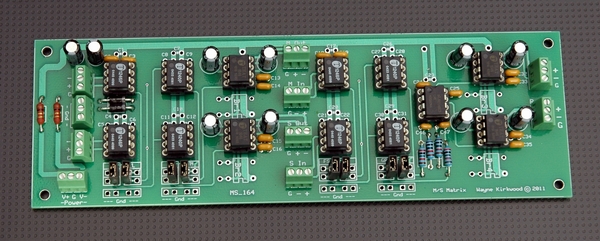
A photo might help too. Note that D1 is installed backwards in the photo. Both really point to the right and the PCB silkscreen is correct. Trust me.

Note that the 5532 -6dB gain stage, in the L and R domain, sits after the 1240 decoder between it and the 1646.
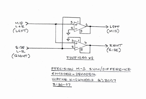
This is the schematic for the 1240 encoder and decoder IC3 and IC4, IC10 and IC11.
The 1246 Input stages look like this. I stole this from the Pico Compressor drawings. Ignore the component designators.
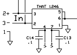
Image stolen from the Pico Compressor Stereo Edition
The 1646 OutSmarts(tm) stages look like this. Ignore the input coupling caps. They are not used and the component designators are bogus.
 If you're going to use the 1646 with single-ended loads make sure the other output is grounded or it will seem noisy.

Image stolen from the Pico Compressor Stereo Edition
This is the 6dB pad in the decoder. One-half shown. That bit about the compensation capacitor being optional I wouldn't take too seriously. Use a 22pF with a 5532.
Want to use a different op amp? Be my guest. I'd keep it bipolar and low noise. This is not the place for a TL072.

MS Mid Side Encoder/Decoder PC Boards: https://ka-electronics.com/shop/index.p ... imple%20MS
Update 5/12/2015:
PDF Assembly Instructions are here: https://www.ka-electronics.com/images/p ... ctions.pdf
Added Mouser Project Manager bill of materials for the Precision MS Matrix.
These lists are not editable but you can "order" the project to move it to your shopping cart, then save the cart as a project to allow editing.
There are two lists one with, and one without, THAT ICs.
I chose an LME49860 for the 5532 location.
There are no bridge rectfiers on the BOM for phantom protection: Most people don't use them.
Without THAT ICs https://www.mouser.com/ProjectManager/P ... 96947b82d5 (material cost as of 9/2/2013 in USD $37.68)
With THAT ICs https://www.mouser.com/ProjectManager/P ... 246710b37f (material cost as of 9/2/2013 in USD $81.88)
Here's a preliminary bill of materials:
13) 8 pin sockets
4) THAT1246 IC1, IC2, IC7, IC8
4) THAT1240 IC3, IC4, IC10, IC11
1) NE5532 IC9
4) THAT1646 IC5, IC6, IC12, IC13
9) 3 pin Phoenix terminal blocks Mouser 651-1725669 (Or 10 if you want a ground tie block)
14) 0.1/100V Mono Ceramic Mouser 581-SR201C104KAR (There are spots for a lot more but 14 are enough)
I stuffed C2, C3, C13-16, C18, C19, C24, C25, C32-35
2) 1R 1/4W R1 and R2(Flameproof/fusible is better but generic carbon film if that's all that's available)
2) 1N4004 D1, D2
8) 10uf radial NP or polarized 25V or greater C38-41, C42-45
2) 47uF/35V C36, C37
2) 22pF/100V Mouser 581-SR151A220JAATR1, C46, C47
2) 10K 1% Mouser 271-10K-RC, R3, R6
2) 20K 1% Mouser 271-20K-RC, R4, R5
4) DB-104 Bridge (optional for phantom power protection) BR1-4
8) 0.1" 2 Pin headers with jumper clips (To bypass various inserts at BR, BL, CS, CM, FS, FM, GR, GL)
Power Supply requirements:
+/-15V to +/-18V at ~ 40 mA. I recommend 18V rails as it buys you slightly more headroom in the Encoder Mid channel.
This is a stuffing guide:
Large format file: http://www.ka-electronics.com/Images/gi ... _large.GIF
The flow diagram. Note that points B, C, F and G correspond to the header connections.
Note that the Encoder and Decoder are interchangeable. For highest accuracy I recommend that the left side be used as the Encoder and the silkscreen is marked that way. For -6dB encoding, the decoder side can be used but it's far less accurate since the 1% MF resistors of the -6dB stage are in the Mid/Side Domain where they affect crosstalk. When the -6dB stage is used in the decoder, the accuracy of the resistors are far less critical since the only affect channel balance by a very small amount.
A photo might help too. Note that D1 is installed backwards in the photo. Both really point to the right and the PCB silkscreen is correct. Trust me.
Note that the 5532 -6dB gain stage, in the L and R domain, sits after the 1240 decoder between it and the 1646.
This is the schematic for the 1240 encoder and decoder IC3 and IC4, IC10 and IC11.
The 1246 Input stages look like this. I stole this from the Pico Compressor drawings. Ignore the component designators.
Image stolen from the Pico Compressor Stereo Edition
The 1646 OutSmarts(tm) stages look like this. Ignore the input coupling caps. They are not used and the component designators are bogus.
If you're going to use the 1646 with single-ended loads make sure the other output is grounded or it will seem noisy.Image stolen from the Pico Compressor Stereo Edition
This is the 6dB pad in the decoder. One-half shown. That bit about the compensation capacitor being optional I wouldn't take too seriously. Use a 22pF with a 5532.
Want to use a different op amp? Be my guest. I'd keep it bipolar and low noise. This is not the place for a TL072.
