New: A Direct-Coupled Input-Capacitorless Active Mic Preamp

Where we discuss new analog design ideas for Pro Audio and modern spins on vintage ones.
olafmatt
Posts: 44
Joined: Wed Oct 22, 2014 11:33 am
Location: Europe

Re: New: A Direct-Coupled Input-Capacitorless Active Mic Preamp

Post by olafmatt »

mediatechnology wrote: Mon Oct 07, 2019 7:48 amOlafmatt's servo that I used in the MC preamp works great at controlling the Vbe offset but I'm not sure it has enough range to also correct the larger offsets the mic presents.
I would guess it would allow for large enough a correction, but it would need less attenuation at the output of the servo opamps, thus potentially adding more unwanted stuff to the signal.

What I was trying to point out a few posts up is that even with my servo, if you make both emitters sit at the same DC offset (i.e. 0VDC across Rg) then due to the bases sitting roughly a fixed 0.65VDC away from the emitters you actually do control the DC offset at the bases. And this means you might still get interaction with the caps in the microphone (if it has some in the output). - And unfortunately with a microphone you never know how large these caps are. In a traditional preamp with phantom blocking caps you can just design around this problem because you have control over the size of the caps.

I remember a story from a few years back with a Universal Audio A/D/A box that had a common mode DC offset leaking out the input because they presumably DC coupled the input XLR to the A/D converter chip which needed a (roughly) 5Vpp swing centred around +2.5V. So the whole frontend was offset by 2.5 volts and SOME mixer outputs didn't like those 2.5V common mode being injected into their outputs. - This is one of the stories that made me aware that an input should always be an input and never "leak" anything out of it.

If the goal would be to simply get rid of phantom blocking caps I'd suggest to design your own mics to go with the preamp and simply use a dedicated power supply wire to the mics. In case we focus on phantom powered microphones, the thing should just work with ANY phantom powered microphone that exists now and might exist at some point in the future.
User avatar
mediatechnology
Posts: 5437
Joined: Sat Aug 11, 2007 2:34 pm
Location: Oak Cliff, Texas
Contact:

Re: New: A Direct-Coupled Input-Capacitorless Active Mic Preamp

Post by mediatechnology »

I would guess it would allow for large enough a correction, but it would need less attenuation at the output of the servo opamps, thus potentially adding more unwanted stuff to the signal.
I intend to find out. I really like the ZTX851 MC front end and with mods I think it will make an excellent mic preamp input-capacitorless or AC-coupled.
What I was trying to point out a few posts up is that even with my servo, if you make both emitters sit at the same DC offset (i.e. 0VDC across Rg) then due to the bases sitting roughly a fixed 0.65VDC away from the emitters you actually do control the DC offset at the bases. And this means you might still get interaction with the caps in the microphone (if it has some in the output). - And unfortunately with a microphone you never know how large these caps are. In a traditional preamp with phantom blocking caps you can just design around this problem because you have control over the size of the caps.
Yes it does reflect back into the bases and thus the output capacitors if the mic is AC-coupled. I think the size of the output caps are limited to 100 uF or less due to stored charge and physical size. At values much larger than 100 uF you can spot-weld. There is the risk of the servo becoming second-order. I think I calculated the worst-case peaking once based on sane output coupling cap values and with some minor tweaking it was manageable.
I remember a story from a few years back with a Universal Audio A/D/A box that had a common mode DC offset leaking out the input because they presumably DC coupled the input XLR to the A/D converter chip which needed a (roughly) 5Vpp swing centred around +2.5V. So the whole frontend was offset by 2.5 volts and SOME mixer outputs didn't like those 2.5V common mode being injected into their outputs. - This is one of the stories that made me aware that an input should always be an input and never "leak" anything out of it.
Must have been the same reference design as my TI A/D EVM board. Its inputs float at Vcm. It's a pain.

Well there's always some bias current leaking in or out of a direct-coupled input.

I look at it this way: From a DC perspective if the output of the mic is a few hundred millivolts out of balance and the servo forces the resistance bridge back into sub-millivolt balance how is that any worse than it being in perfect balance to begin with?
olafmatt
Posts: 44
Joined: Wed Oct 22, 2014 11:33 am
Location: Europe

Re: New: A Direct-Coupled Input-Capacitorless Active Mic Preamp

Post by olafmatt »

mediatechnology wrote: Mon Oct 07, 2019 2:11 pmI look at it this way: From a DC perspective if the output of the mic is a few hundred millivolts out of balance and the servo forces the resistance bridge back into sub-millivolt balance how is that any worse than it being in perfect balance to begin with?
It can even be a good thing! If you have a mic with output transformer and the phantom voltage picked up with resistors (no center tap on the transformer) the servo would help to reduce core saturation which you'd normally get with too much DC offset being left in place.

Probably I'm just worried about potential mics with DC servos in their output.

About the CM offset, yes that TI A/D EVM board does the same. As does the ARDA AT1201 EVM board. Seems to be quite common because it lowers parts count and gives better meassurement results. And as long as it works prilliantly with lab equipment on a tidy bench, who cares? :evil:
User avatar
mediatechnology
Posts: 5437
Joined: Sat Aug 11, 2007 2:34 pm
Location: Oak Cliff, Texas
Contact:

Re: New: A Direct-Coupled Input-Capacitorless Active Mic Preamp

Post by mediatechnology »

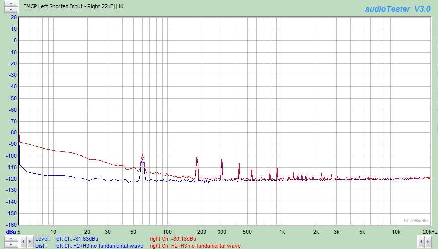
I decided to revisit the argument I've previously made regarding the 1/f noise effects of having input coupling capacitors versus direct-coupling of mic preamp inputs.

I decided to use the Flat Moving Coil Preamp since its a finished circuit board.
The input noise voltage is exceptionally low, at around 400pV√Hz, owing to the ZTX851's low rbb and low value resistors in the supporting circuitry.
The current noise is fairly high since its an MC preamp with high collector current and input transistor Hfe around 130-200.
I estimate the current noise density to be about 4pA√Hz.

The preamp's servo is turned of to extend response to DC.
The Focusrite 2i2 is flat to around 2Hz or so and it has a noise corner around 4-5 Hz.
The preamp's noise corner begins below about 5 Hz with a shorted input.
With a 22uF capacitor across the input, in parallel with the 1K differential resistance of the bias resistors, a significant 1/f increase is seen from added reactance.
22uF was chosen because it is roughly equal to having two 47uF input coupling caps in series.

The red trace shows the increase in LF noise due to the capacitor.

Image
Comparing input coupling capacitors to direct coupling's effects on 1/f noise.

Adding additional resistance to represent source impedance shifts both curves upward but large differences remain with typical 150Ω source impedances.
emrr
Posts: 569
Joined: Sun Mar 02, 2008 10:27 pm
Location: NC, USA
Contact:

Re: New: A Direct-Coupled Input-Capacitorless Active Mic Preamp

Post by emrr »

Adding additional resistance to represent source impedance shifts both curves upward but large differences remain with typical 150Ω source impedances.
Do those shifted differences track with this plot, or is the effect increased?

This looks like 12dB difference at 50Hz, 6dB at 100Hz. In the zone where the ear usually doesn't care or notice much - but I wouldn't dismiss the value on that basis without listening tests various sources, mics, gain amounts.

I'm trying to think where else this low frequency noise increase might cause unexpected results, I would guess more in instrumentation applications, seismic applications, full range ambient capture, etc. For most music applications with HPF's of any type applied, I'm unsure.
Best,

Doug Williams
Electromagnetic Radiation Recorders
User avatar
mediatechnology
Posts: 5437
Joined: Sat Aug 11, 2007 2:34 pm
Location: Oak Cliff, Texas
Contact:

Re: New: A Direct-Coupled Input-Capacitorless Active Mic Preamp

Post by mediatechnology »

I ran curves with an additional 150Ω source impedance added and the noise baseline increased on both as expected and the spread between curves decreased but still existed.

I'm not sure how much this matters in a mic preamp - particularly with a HP filter used - but the one application where it is significant is the phono preamp with the 20 dB at 20 Hz RIAA boost.

I want to experiment with much lower value input Cs to emulate using film caps e.g. 4.7uF per leg for a net total of 2.35 uF.
User avatar
mediatechnology
Posts: 5437
Joined: Sat Aug 11, 2007 2:34 pm
Location: Oak Cliff, Texas
Contact:

Re: New: A Direct-Coupled Input-Capacitorless Active Mic Preamp

Post by mediatechnology »

I should also add that we do not see noise from capacitor leakage current when phantom is applied.

That's an another area of inquiry I'd like to pursue.
emrr
Posts: 569
Joined: Sun Mar 02, 2008 10:27 pm
Location: NC, USA
Contact:

Re: New: A Direct-Coupled Input-Capacitorless Active Mic Preamp

Post by emrr »

Makes sense, thanks
Best,

Doug Williams
Electromagnetic Radiation Recorders
olafmatt
Posts: 44
Joined: Wed Oct 22, 2014 11:33 am
Location: Europe

Re: New: A Direct-Coupled Input-Capacitorless Active Mic Preamp

Post by olafmatt »

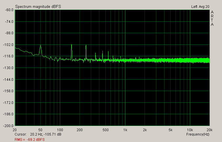
Sorry that I'm a little late to the party. - After having experimented with a input-cap-less micpre circuit for a while I went back to using caps to avoid a bunch of potential problems. Tried instead to minimize the impact that those phantom blocking caps have.

Here is the noise floor of a micpre with 2u2 DC blocking caps (at 65db gain and terminated with 150 ohms and please ignore the mains hum):

Image

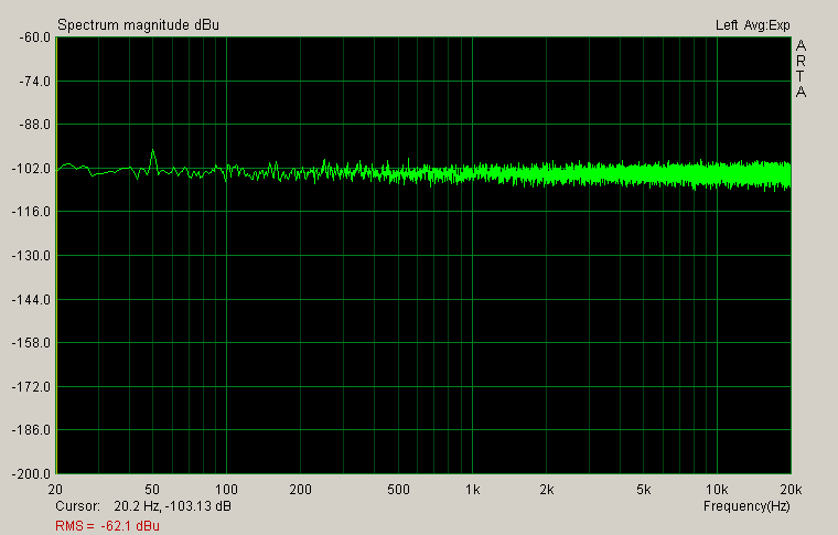
Those caps are nicely small, but because of the rising noise floor at low frequencies the next iteration got 22u caps (and reduced R to keep the LF corner frequency the same). Again 65db and 150 ohms (but I forgot to enter the dbFS level of the ADC, so please ignore the dBu scale):

Image

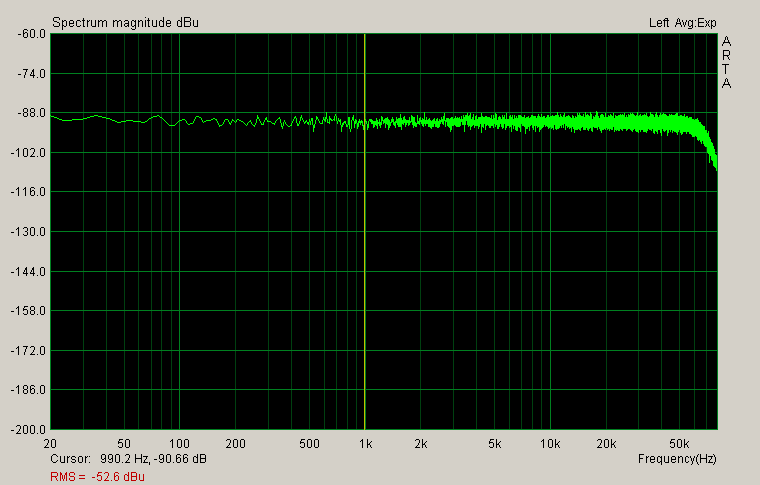
And here the same circuit with fake MAT02 transistors instead of genuine LM394:

Image

While investigating the effects of the DC blocking caps and playing with T-bias (which means higher common-mode input impedance than differential input impedance), I also realized that a mic that starts to draw more phantom power (due to high SPL) can make the phantom voltage sag a little. Due to the higher common-mode impedance this can then "modulate" the common-mode "offset" at the input transistors. Since the common-mode gain of the frontend is 1, the effect is a change in collector-base voltage. To reduce the impact that has, I then went with a bootstrapped cascode as input (tricky to prevent from oscillating...).

In that regard, a DC-blocking-cap-less preamp has the advantage that also the supply voltages for the frontend follow any common-mode changes in phantom voltage. You're sort of bootstrapping the whole gain circuit.
User avatar
mediatechnology
Posts: 5437
Joined: Sat Aug 11, 2007 2:34 pm
Location: Oak Cliff, Texas
Contact:

Re: New: A Direct-Coupled Input-Capacitorless Active Mic Preamp

Post by mediatechnology »

Thanks for posting. It's been awhile for sure.

The image links are http and some browsers (mine) won't display them but you can open them by right-clicking the broken image icon and opening them in a new tab.

It looks like the 22 uF version has a flat, but higher noise curve than the 2.2 uF which has the expected rising 1/f. Is that due to the dBFS/dBu gain offset?

Those fake MAT-02 are really bad. Looked at the AS394?

The CM modulation at higher SPLs is likely high in even-order. I've seen the same effect.

For the input-capacitorless preamp I've pretty much decided to pursue a dual servo system the first of which would minimize gross offset at the input from current imbalance. The input itself would be the sample point and the control point would vary phantom current. This servo would require a long time constant.

The second servo would only be used to minimize delta-Vbe offset at Rg to reduce clicking. What I finally used for the second MC preamp that controls Ie works really well with servo Fc constant with gain.

Whether the two servos interact and fight each other remains to be seen.
Post Reply