New: A Direct-Coupled Input-Capacitorless Active Mic Preamp

Where we discuss new analog design ideas for Pro Audio and modern spins on vintage ones.
User avatar
JR.
Posts: 3697
Joined: Sat May 24, 2008 7:21 pm
Contact:

Re: New: A Direct-Coupled Input-Capacitorless Active Mic Preamp

Post by JR. »

mediatechnology wrote: Fri Feb 15, 2019 10:00 am The earliest reference I found to the TL431 was its predecessor the TL430 in 1978. So about 41 years.
By about 1980 the TL431 was found in the Apple II power supply.

JR I do value your input. Until 2018 I had overlooked the TL431.
Glad I tried it.
In the current shunt monitor it rocks.
I think its just better to try something and piss on it if it doesn't work than just piss on it and never know.
[edit]

I agree we should be more receptive to new ideas.

I soaked this in beer last night and have some new thoughts. More new stuff this AM (without the beer).

JR
I like the floating A/D if no analog out is needed.
Since there are two data paths that need to cross the galvanic barrier, audio and control, it would be cool if a single UART that embeds control into audio could be used so that only one bidirectional opto-coupler or data transformer is needed.
Would DANTE lend itself to that?
Cancel the "cancel culture", do not support mob hatred.
User avatar
JR.
Posts: 3697
Joined: Sat May 24, 2008 7:21 pm
Contact:

Re: New: A Direct-Coupled Input-Capacitorless Active Mic Preamp

Post by JR. »

After thinking about an op amp substitute for my 3-put I though of a couple ways.

Summing the two floating outputs should remove AC (audio) and capture the DC offset we need to subtract out. Sending the floating voltage audio DC coupled into simple grounded inverting op amps, then adding in an inverted version of the CM DC voltage we should realize a DC coupled 0V referenced output.

In principle simply summing the two floating audio legs should cancel out the audio leaving just the DC. This summed DC term could be inverted and subtracted from each leg at the output inverters to ground reference the remaining audio. This is all without capacitors while I am tempted to help cancel out the audio with a cap there (like my 3 put did). An imperfect audio cancellation should not cause too much harm (?) to the audio integrity.

Another design consideration for this approach is keeping the noise gain and signal integrity of the output drivers (very) good. One trick to keep the noise gain of the output op amps low would be to generate a -60V supply to facilitate a -48V DC subtraction signal voltage and only realize a noise gain of 3x (10dB) in those output amps. The noise gain could be held to only 6dB using a current source to subtract out the offset term, but then we have the noise of that current source to worry about. :roll:

With modern high performance opamps 10 dB of noise gain should be tolerable, at the output of a mic preamp.
===
Another approach is to apply a DC servo to the outputs of the DC coupled output op amps. The servo could look at the CM voltage from both output op amps together and apply a single error correction signal. Again the noise gain of the output op amps is a factor. Servo's seem more acceptable to audiophiles than cap coupled stages even though at high level the caps in cap coupled stages can be arbitrarily high quality. Again we can look at a servo with no cap? That just sounds weird. :roll:
----

Another way to do this without any capacitors is using a microprocessor to capture the DC offset, and calculate a correction voltage/current to apply. This is actually a digital analog of a smoothing capacitor (admittedly using lots of cheap transistors). A long time ago I speculated about using a micro to tweak things like input stage current density based on a noise measurement algorithm. Maybe even variable phantom voltage (as needed to bias up the inputs to some nominal voltage) but this is getting a bit excessive.

FWIW a better managed phantom voltage could relax the voltage required for our cancellation.

I won't melt any solder proving these variants either (just more mental masturbation for me).

JR
Cancel the "cancel culture", do not support mob hatred.
User avatar
mediatechnology
Posts: 5437
Joined: Sat Aug 11, 2007 2:34 pm
Location: Oak Cliff, Texas
Contact:

Re: New: A Direct-Coupled Input-Capacitorless Active Mic Preamp

Post by mediatechnology »

JR. wrote: Sun Feb 17, 2019 10:48 am After thinking about an op amp substitute for my 3-put I though of a couple ways.

Summing the two floating outputs should remove AC (audio) and capture the DC offset we need to subtract out. Sending the floating voltage audio DC coupled into simple grounded inverting op amps, then adding in an inverted version of the CM DC voltage we should realize a DC coupled 0V referenced output. (emphasis added.)

JR
May have been down this road...
How much current do you have to do this?
I recall in the early days of this discussion over at Prodigy-Pro the point being raised about "burning off" common mode DC via a differential stage or some other means of subtraction.
If you make the resistors low enough for low noise the power dissipation is high.
Make the resistors too high and the noise degrades.

I think burning off common mode is where many people abandoned a fully DC-coupled method.
IIRC Chalupa used that approach.
It's been 12 years but I think Olaf was the one who brought that up.

If you look at this block diagram, the only part that's unique to being input-capacitorless is the common mode servo. (Shown at bottom.)

Image
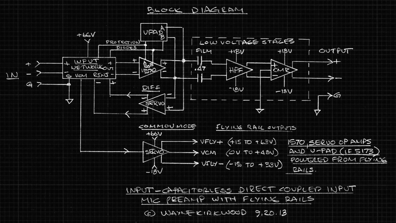
Input-Capacitorless Preamp Overall Block Diagram

Most of the "stuff" is "stuff" you'd have in there anyway.

The only real added part is the servo shown here:

Image
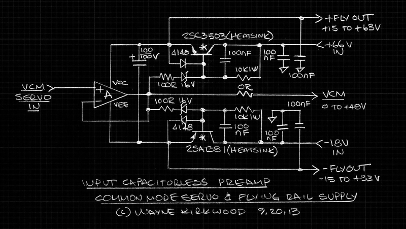
Input-Capacitorless Preamp Feed-Forward Common Mode Servo With Bootstrapped Flying Rail Supply

The two resistors and the film cap used to sense the input Vcm are not shown on this drawing. See: viewtopic.php?f=6&t=598#p6865

The only significant circuitry required to pull off the Vcm servo is an op amp, two transistors and two Zeners.
Maybe there's a simpler way to do it?

I had once thought about using a specialized switcher with a floating auxiliary secondary.
A second center-tapped transformer and +/-15V split supply would float up to Vcm.
The +/-15V floating supplies would bracket around Vcm just like they do now.
Driving the transformer CT would likely require the same buffer as would be used to drive the existing servo/bracketing supply.
The only advantage might be less wasted power.

Is there a solution that's simpler than an op amp and two medium-power transistors?
Maybe use 2X TL431's instead of Zeners? :lol:
Oh wait that adds 4X resistors, never mind. :oops:

Seriously, how much simpler can this be?

The other thing is you still want is good old-fashioned AC-coupling for a defined high-pass filter.

Without regard to an offset-correcting servo being a high pass filter you really want something to filter the infrasonic or the subway.
There's no point in response to DC unless you're recording strain gauges or earthquakes.

So whether the output is feeding an analog Pultec, a floating converter, or a tin cup attached to a string you still want an analog film-capcitor-based high pass filter to keep from recording or transmitting out-of-band DR-robbing LF rumble.
Maybe you don't want it all the time but you definitely want the button.

You just can't beat a capacitor (or two) for the high-pass function.

At the end of the day all we're doing is moving the coupling caps from the input to the output to make them smaller and film.
The other benefits might be lower equivalent source resistance and removal of stored DC charges from the input transistors.
Whatever added benefits we get from that is fine.
I think that's it in a nutshell: We're just using an op amp to move the coupling caps.
User avatar
JR.
Posts: 3697
Joined: Sat May 24, 2008 7:21 pm
Contact:

Re: New: A Direct-Coupled Input-Capacitorless Active Mic Preamp

Post by JR. »

mediatechnology wrote: Sun Feb 17, 2019 12:25 pm
I think that's it in a nutshell: We're just using an op amp to move the coupling caps.
Kind of like a servo?

JR
Cancel the "cancel culture", do not support mob hatred.
User avatar
mediatechnology
Posts: 5437
Joined: Sat Aug 11, 2007 2:34 pm
Location: Oak Cliff, Texas
Contact:

Re: New: A Direct-Coupled Input-Capacitorless Active Mic Preamp

Post by mediatechnology »

JR. wrote: Sun Feb 17, 2019 12:47 pm
mediatechnology wrote: Sun Feb 17, 2019 12:25 pm
I think that's it in a nutshell: We're just using an op amp to move the coupling caps.
Kind of like a servo?

JR
Bingo!
Exactly the same "analog."
Make a little film capacitor act like a big one.

Servo in feed-forward...
User avatar
mediatechnology
Posts: 5437
Joined: Sat Aug 11, 2007 2:34 pm
Location: Oak Cliff, Texas
Contact:

Re: New: A Direct-Coupled Input-Capacitorless Active Mic Preamp

Post by mediatechnology »

I often go back through old data books and application notes and when I do always see something I've missed or see an old idea that may be applicable in a completely different area. Today was one of those days.

While quick-reading Burr Brown's 1987 "The Handbook of Linear IC Applications" I found an article "Tame Transducer Bridge Errors With Op Amp Feedback Control." I think you can see, in the context of a mic preamp where this may be headed...

Over the years I've looked at all kinds of methods to servo-correct gross differential DC offsets at the mic terminals and servo mic preamps in general. Not sure this is a complete list but here are some:

1) Inject current into the input stage bases.
2) Shift the emitter currents by differentially-controlling the emitter current sinks.
3) Offset the collector load resistor voltage/collector current.
4) Put an LDR on one input leg. (CMRR-busting. Detailed in original thread.)

Techniques 1-3 all work some have more advantages than others. Methods 1-3 deferentially shift the input stage current density.
Method 4 alters the resistive bridge balance.

"Tame Transducer Bridge Errors With Op Amp Feedback Control," though it doesn't show the example, gave me one more idea to try:

Vary the voltage on the top-side of the phantom pull-up resistors slightly to bring the mic output into balance.

Duh, should've thought of that one before - it has the advantage of being able to correct large errors (tens of millivolts) by balancing the bridge nearest the node the imbalance occurs. It also has the advantage of not pulling the transistor operating currents to correct input imbalances.

The ZTX851 Moving Coil Preamp shows that theses very low rbb' devices will also make a good mic preamp and the fixed fc servo it uses works well at controlling input stage offsets.
The servo the MC preamp uses however may not have enough pull range to correct phantom imbalances.
A combination of servos, a slow one to correct large DC input offsets with phantom on, and a faster-response servo to correct input stage errors may be a better solution.

With the ZTX851 Moving Coil preamp almost "in the can" it may be time to revisit the input-capacitorless preamp.
User avatar
JR.
Posts: 3697
Joined: Sat May 24, 2008 7:21 pm
Contact:

Re: New: A Direct-Coupled Input-Capacitorless Active Mic Preamp

Post by JR. »

mediatechnology wrote: Sat Jul 13, 2019 4:52 pm I often go back through old data books and application notes and when I do always see something I've missed or see an old idea that may be applicable in a completely different area. Today was one of those days.

While quick-reading Burr Brown's 1987 "The Handbook of Linear IC Applications" I found an article "Tame Transducer Bridge Errors With Op Amp Feedback Control." I think you can see, in the context of a mic preamp where this may be headed...

Over the years I've looked at all kinds of methods to servo-correct gross differential DC offsets at the mic terminals and servo mic preamps in general. Not sure this is a complete list but here are some:

1) Inject current into the input stage bases.
not unlike fixed trims through hi z resistors.
2) Shift the emitter currents by differentially-controlling the emitter current sinks.
logical for modest trims... something like 3mV Vbe shift for doubling/halving of current density (IIRC?).
3) Offset the collector load resistor voltage/collector current.
I have also used DC coupled feedback Rs so current density of input pair could be varied by DC voltage of that first gain stage. Of course undesirable for fully DC coupled path. :oops:
4) Put an LDR on one input leg. (CMRR-busting. Detailed in original thread.)
Pass.... but in my later cognitive decline I have thought about using DPOTs and microprocessor control for smart tweaks under cybernetic control. (In one feverish dream I even considered varying input stage current density while measuring output noise to perhaps optimize for mic source impedance.)
Techniques 1-3 all work some have more advantages than others. Methods 1-3 deferentially shift the input stage current density.
Method 4 alters the resistive bridge balance.
I am not aware of major downside to input pair current density mismatch, within reason... in extremes I could imagine several parameters degrading.
"Tame Transducer Bridge Errors With Op Amp Feedback Control," though it doesn't show the example, gave me one more idea to try:

Vary the voltage on the top-side of the phantom pull-up resistors slightly to bring the mic output into balance.
I have thought about varying that voltage (both Rs at the same time) to drop the floating input voltage down to more manageable voltages (within +/-18V). Mostly mental masturbation and I could imagine issues, never melted solder.

I suspect many, but not all mics could operate from much lower than 48V phantom. In fact grounding the 6.81k resistors, and dumping phantom power as current sources to power mic innards, is another variant on that theme that could make floating DC voltage more manageable. (Involves driving pin 1 negative, another invitation for unexpected field problems.)
Duh, should've thought of that one before - it has the advantage of being able to correct large errors (tens of millivolts) by balancing the bridge nearest the node the imbalance occurs. It also has the advantage of not pulling the transistor operating currents to correct input imbalances.
You are miles ahead of my mostly theoretical musings about issues with specific mics.
The ZTX851 Moving Coil Preamp shows that theses very low rbb' devices will also make a good mic preamp and the fixed fc servo it uses works well at controlling input stage offsets.
The servo the MC preamp uses however may not have enough pull range to correct phantom imbalances.
A combination of servos, a slow one to correct large DC input offsets with phantom on, and a faster-response servo to correct input stage errors may be a better solution.

With the ZTX851 Moving Coil preamp almost "in the can" it may be time to revisit the input-capacitorless preamp.
Why not... I tried to get APB interested but they weren't and they have (had?) tweaky analog console customer base. Those customers jumped ship when digital mixers that don't suck got crazy cheap.

I still kind of like the idea of letting the DC coupled mic pre float up to whatever voltage it wants and then perform the A/D up at the elevated voltage wherever that lands. The digital output could optically transfer down to normal rails. The trouble with this is you become married to one A/D convertor..

Perhaps a good strategy for somebody already selling exotic stand alone A/D convertors.

JR
Cancel the "cancel culture", do not support mob hatred.
User avatar
mediatechnology
Posts: 5437
Joined: Sat Aug 11, 2007 2:34 pm
Location: Oak Cliff, Texas
Contact:

Re: New: A Direct-Coupled Input-Capacitorless Active Mic Preamp

Post by mediatechnology »

I first proposed an "input capacitorless" preamp back in 2007 on another fora. At the time I recall Gus mentioning that he had seen a floating input instrumentation amp published. If I remember correctly he thought the source was either TI or Burr Brown.

I may have found the Burr Brown example in the 1994 Burr Brown "Applications Handbook."

The flying supply rails are provided by A6 and A7 which bracket the INA's +/-5V supply voltages around Vcm. A6 and A7 are HV op amps. The REF200s simply provide an offsetting current to ultimately offset the A6 and A7 outputs by 5V from Vcm.

In this example the DC common mode voltage is "burnt off" by A3 and R1-R4. "Burning off" Vcm in a mic preamp is impractical since the low-value resistors required for low noise around A3 also require high power dissipation.

Image
High Voltage Instrumentation Amp Burr Brown Applications Handbook 1994 Page 70.

Image
High Voltage Instrumentation Amp Burr Brown Applications Handbook 1994 Page 70 Text.
User avatar
JR.
Posts: 3697
Joined: Sat May 24, 2008 7:21 pm
Contact:

Re: New: A Direct-Coupled Input-Capacitorless Active Mic Preamp

Post by JR. »

mediatechnology wrote: Sat Jul 20, 2019 7:18 am I first proposed an "input capacitorless" preamp back in 2007 on another fora. At the time I recall Gus mentioning that he had seen a floating input instrumentation amp published. If I remember correctly he thought the source was either TI or Burr Brown.

I may have found the Burr Brown example in the 1994 Burr Brown "Applications Handbook."

The flying supply rails are provided by A6 and A7 which bracket the INA's +/-5V supply voltages around Vcm. A6 and A7 are HV op amps. The REF200s simply provide an offsetting current to ultimately offset the A6 and A7 outputs by 5V from Vcm.

In this example the DC common mode voltage is "burnt off" by A3 and R1-R4. "Burning off" Vcm in a mic preamp is impractical since the low-value resistors required for low noise around A3 also require high power dissipation.

I learned a bunch from my "Burr Brown Operational Amplifiers design and application" text C.1971
======
I am not so sure that power dissipation is the only or major problem. The mic signal has already been well amplified by this point, so resistor values do not need to be crazy low to maintain decent signal integrity. The larger problem IMO is that this differential level shifter must be able to handle far more voltage than typical 36V process op amps would support.

Years ago I scratched up my "3-put" (three transistor LTP input, two output DOA) to perform such a level shift task.

Still impractical (and I never melted solder over this) as by this time you can level shift the already amplified signal, capacitor coupled using decent quality film capacitors with no apparent sound quality compromise (as Wayne has demonstrated).

If an audiophile is such a purist they cannot tolerate even one (good) capacitor in their audio path, they need to take up a different hobby. Many microphones have capacitors in their path, and what would you play the audio output through that doesn't have capacitors?

JR
Cancel the "cancel culture", do not support mob hatred.
olafmatt
Posts: 44
Joined: Wed Oct 22, 2014 11:33 am
Location: Europe

Re: New: A Direct-Coupled Input-Capacitorless Active Mic Preamp

Post by olafmatt »

Just checking in very infrequently, so noticed this just now...
mediatechnology wrote: Sat Jul 13, 2019 4:52 pmVary the voltage on the top-side of the phantom pull-up resistors slightly to bring the mic output into balance.

Duh, should've thought of that one before - it has the advantage of being able to correct large errors (tens of millivolts) by balancing the bridge nearest the node the imbalance occurs. It also has the advantage of not pulling the transistor operating currents to correct input imbalances.
IIRC we once talked about this option (might have been in email, though). - I don't see much difference between varying the voltage at the top of the phantom resistors compared to the very traditional way of injecting servo current through resistors into the bases. Sinking/sourcing current using extra resitors will cause some current through the phantom resitors resulting in the desired voltage change at the bases.
And in both cases your servo correction is subject to the (varying) gain of the preamp (resulting in changes of the corner frequency).

To me it seems counter intuitive to fix a mirophone probem (DC offset at it's output, and here I consider the phantom resistors to be pa "part" of the microphone) inside a mic-preamp. A (theoretical) more elegant solution would be to "just" design / choose a preamp circuit that can survive the fact that a microphone has/might have a DC offset on it's output.
So you need a preamp circuit that has a DC gain of 0dB no matter what the AC gain is. Since we don't want a cap in series with Rg, this is probably not going to happen. So next option is to make the DC offset cancel with something inside the preamp circuit (instead of trying to force the microphone output to be "correct"). Maybe one could come up with a preamp circuit with two inputs that get summed together. That way you could use the second input to inject the inverse of the DC offset generated my the microphone.

Another thing is that we don't like the DC offset with 60dB of gain applied because we get a problem with the required voltage swing. Maybe if the output of the first preamp section would be a current we could circumvent this problem. That ouput current could be fed into a summing amp (virtal ground) together with the aforementioned correction current to get rid of the DC offset.

Looking back at how all this started, you selected in integrated preamp (a "black box") and tried to design the sourrounding circuitry to make it work. And because of that you need to servo the DC at the input instead of somewhere (and "somehow") inside.
Post Reply